
My S13 SR20DET Prep
 05-13-2008, 03:37 PM
#166
Contributing Member
Thread Starter
Join Date: Sep 2002
Location: Starkville, MS.
Posts: 1,192
Transmission-Gasket Replacement Continued...
I received my gaskets and seals today from Courtesy Nissan.
Tools needed:
Socket wrench
Socket extension
12mm socket
Seal puller
Seal driver
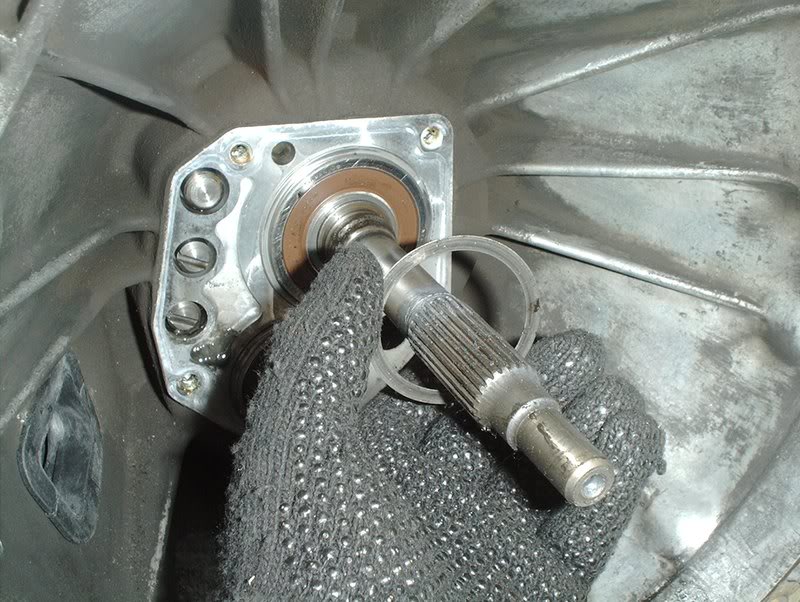
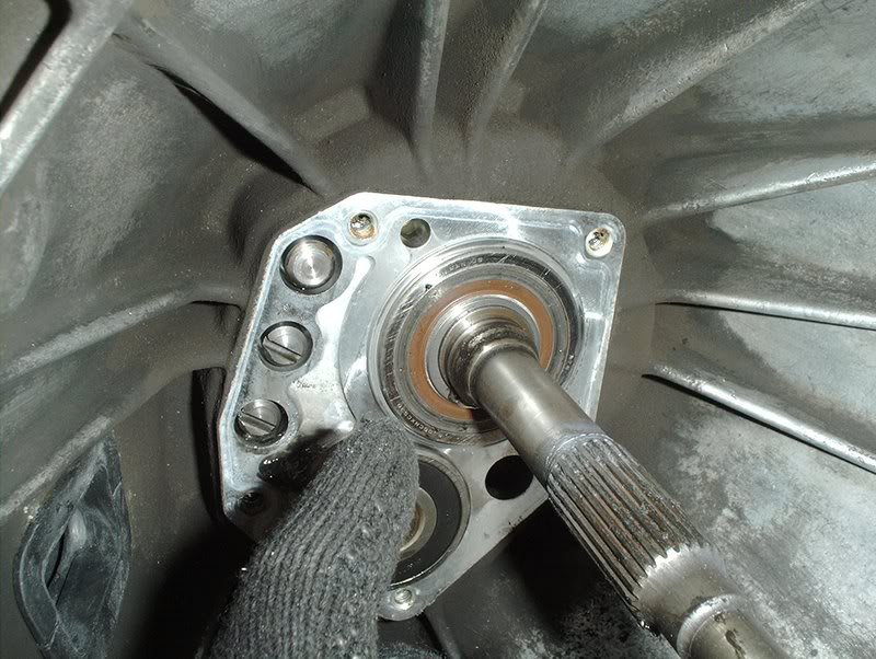
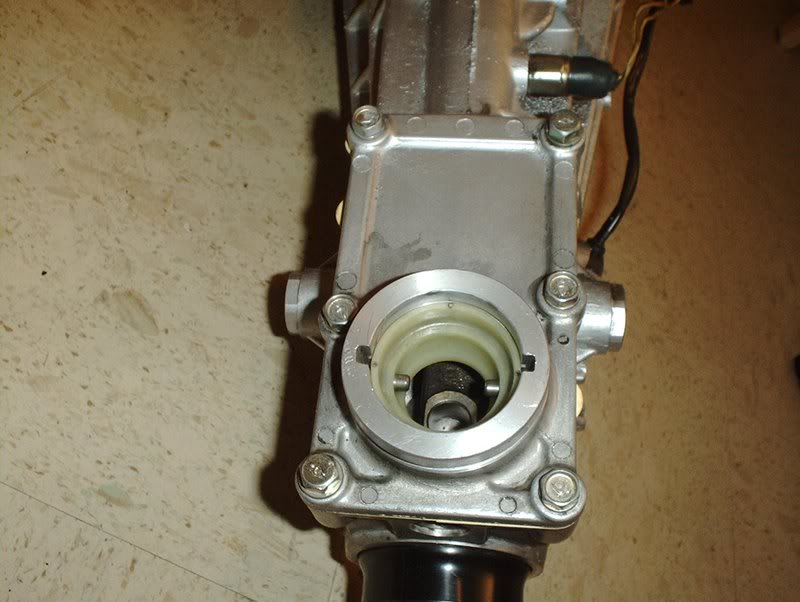
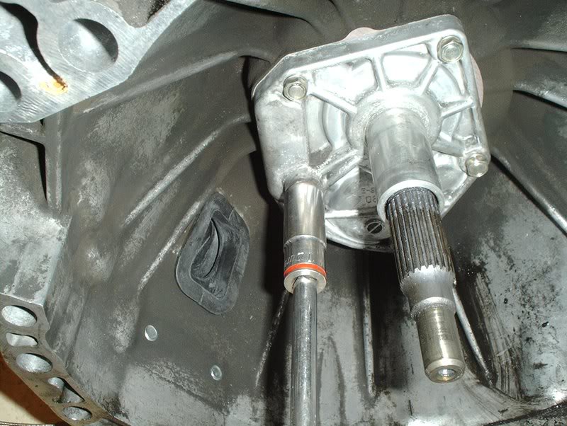
I started with the front transmission cover gasket. I was planning to swap out the front transmission seals also but I couldn't see any way to easily remove these seals without completely dissassembling the transmission and removing the shaft in order to gain access to them.
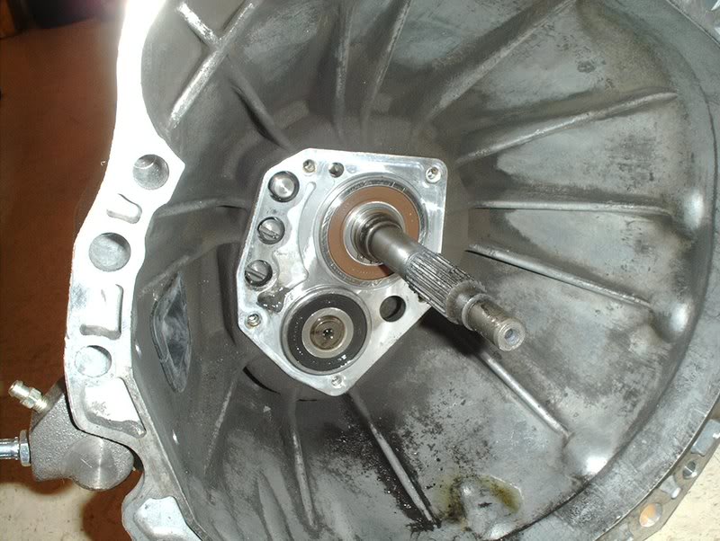
The seals under the front cover appear to be in perfect condition anyway so I just decided to roll the hard six and skip replacing them.
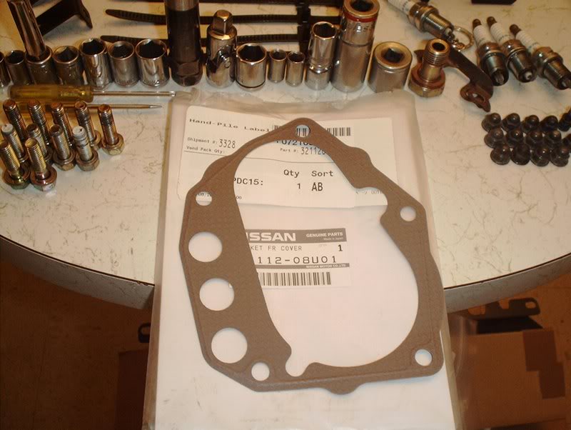
Front transmission cover gasket. Part#:32112-08U01
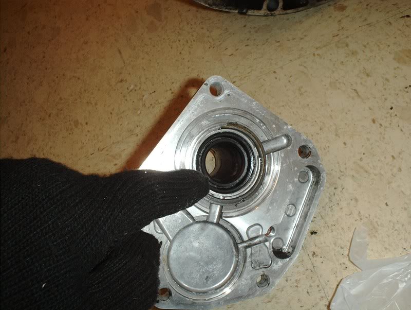
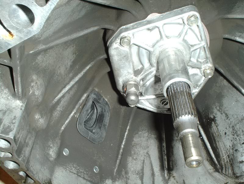
I removed the front cover earlier and as you can see it was quite filthy, covered in grease.
I got some Mean Green and a scrub brush, cleaned it up and regreased it. I hate handling dirty parts.
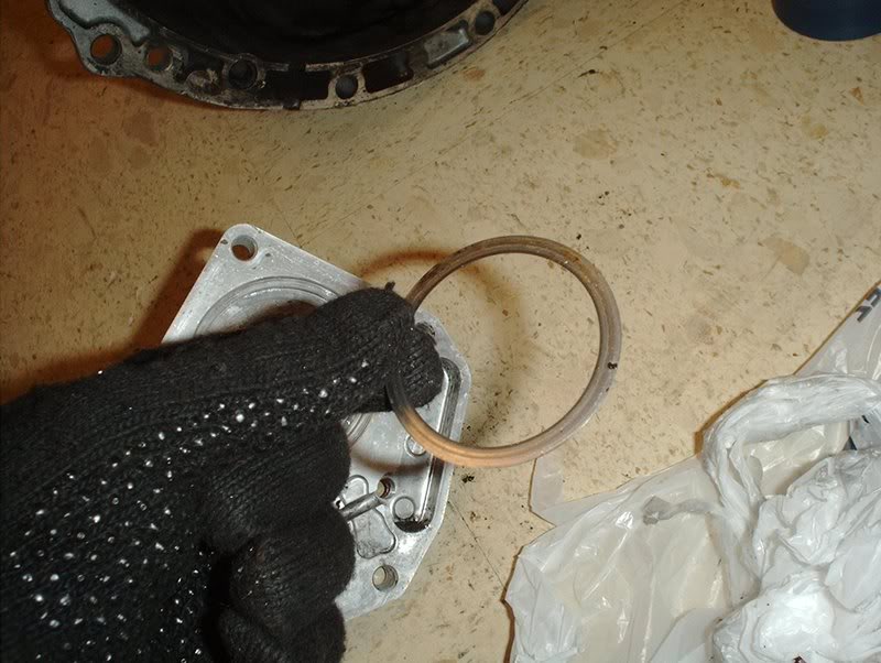
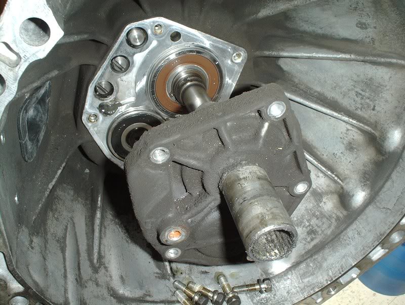
Start by taking the O-ring and putting it in place.
It will go here.
Take the O-ring...
and place it on the seal, it will stay in place when you put the front cover on.
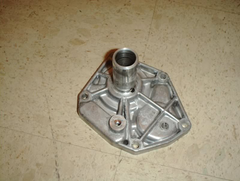
Take a 12mm socket and replace the 5 bolts on the front cover. Torque them to 12-15ft.lbs.
Done.
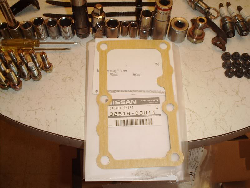
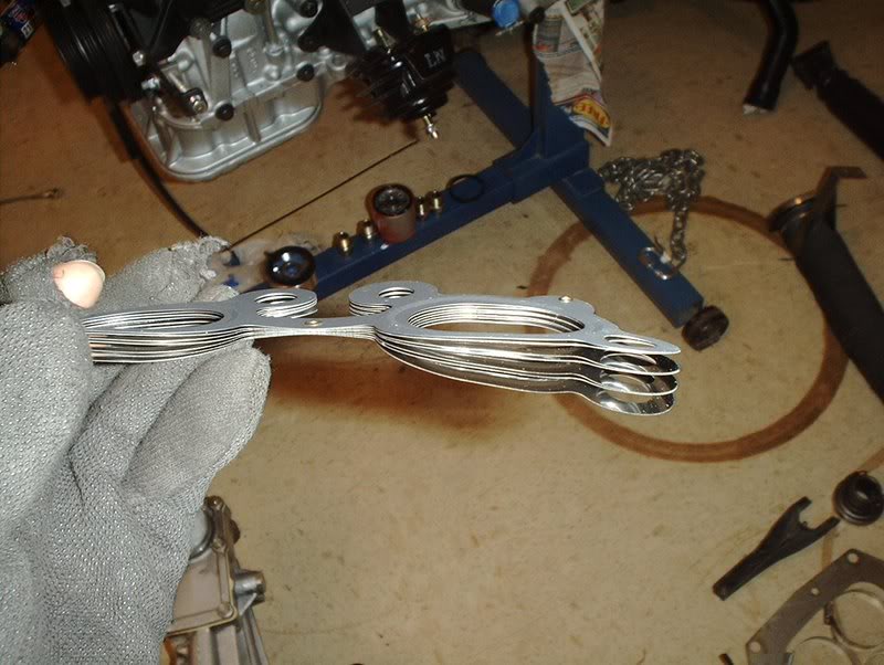
Next, I replaced the gearbox gasket. Part#: 32516-03U11.
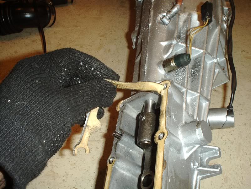
I pulled the old gasket off.
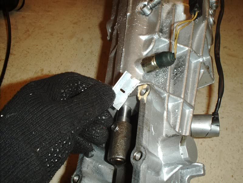
Use a razorblade to remove all traces of the old gasket.
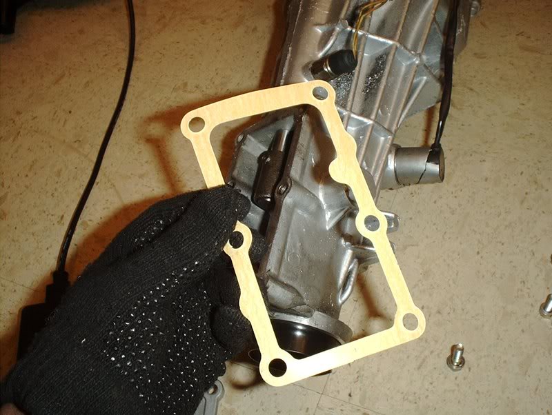
Take the new gasket...
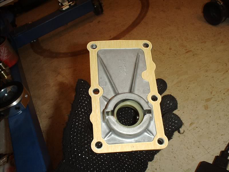
and place it on the underside of the gearbox cover...
and place it on the transmission.
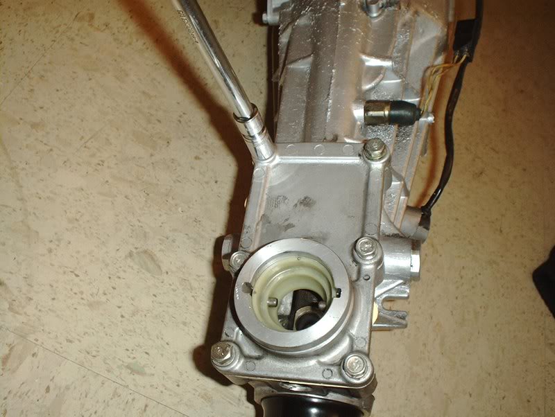
Use a 12mm socket to replace the six bolts. Tighten them in a similar fashion to the valve cover bolts and torque to 10-13ft.lbs.
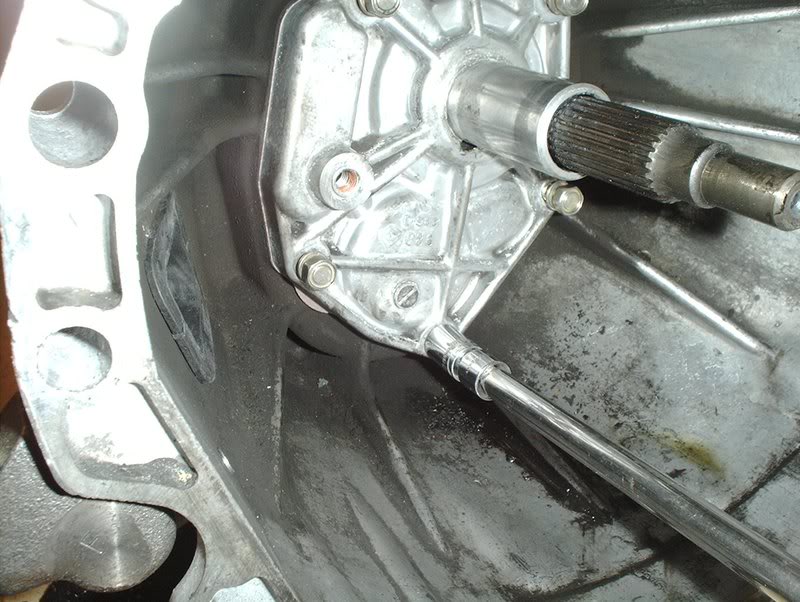
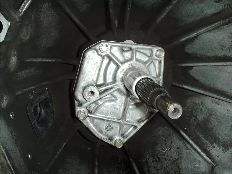
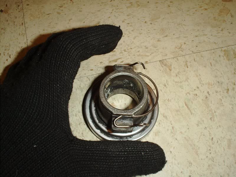
I also replaced the transmission rear seal.
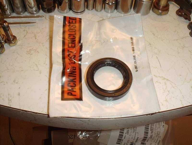
Transmission rear seal. Part#: 32136-U0100.
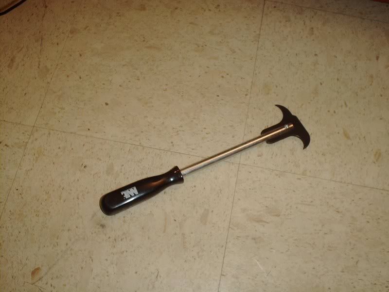
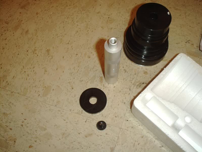
Seal puller. Wish I had this when I did the front main oil seal.
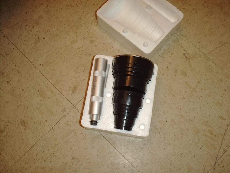
Seal driver kit. This too!
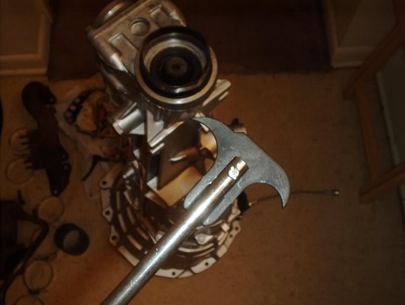
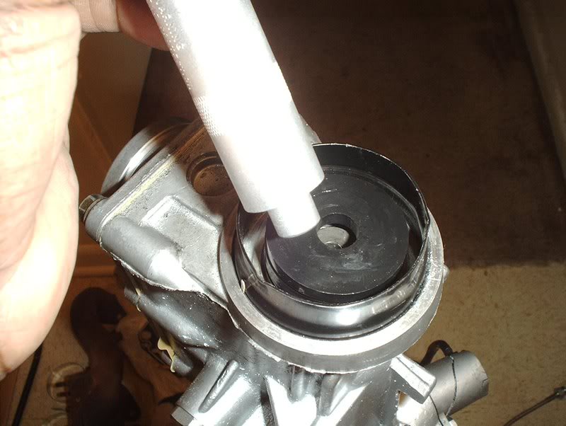
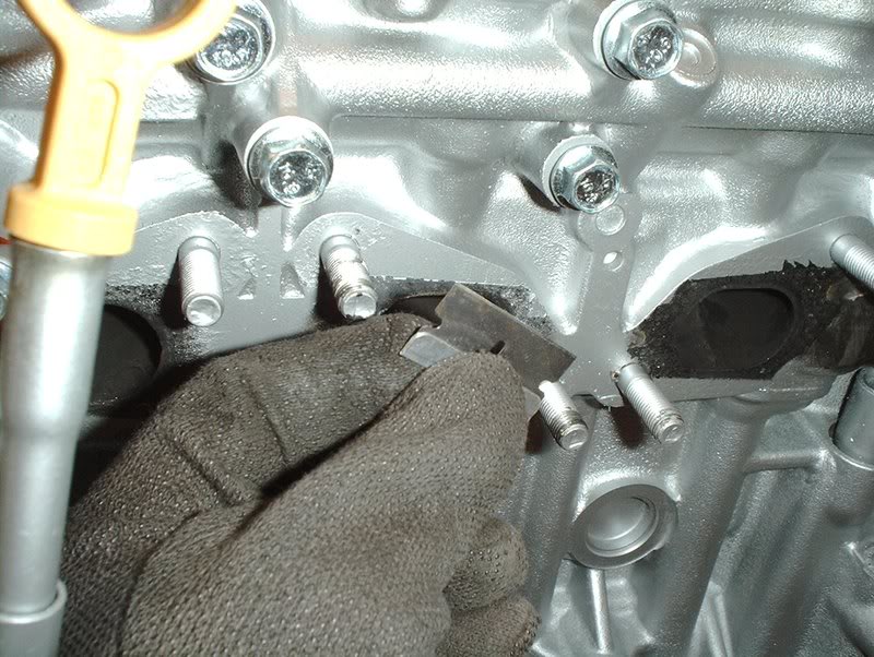
Take your seal puller or you could use a prybar or flathead screwdriver and place it around the inside of the seal.
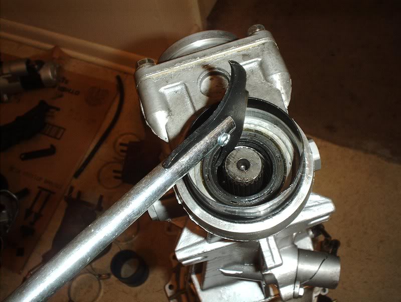
Like so.
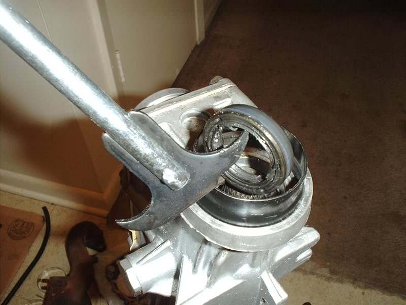
Pull the old seal out.
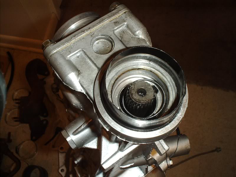
Clean the area.
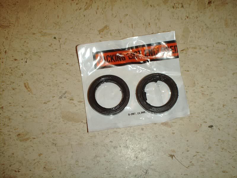
New seal and the old seal.
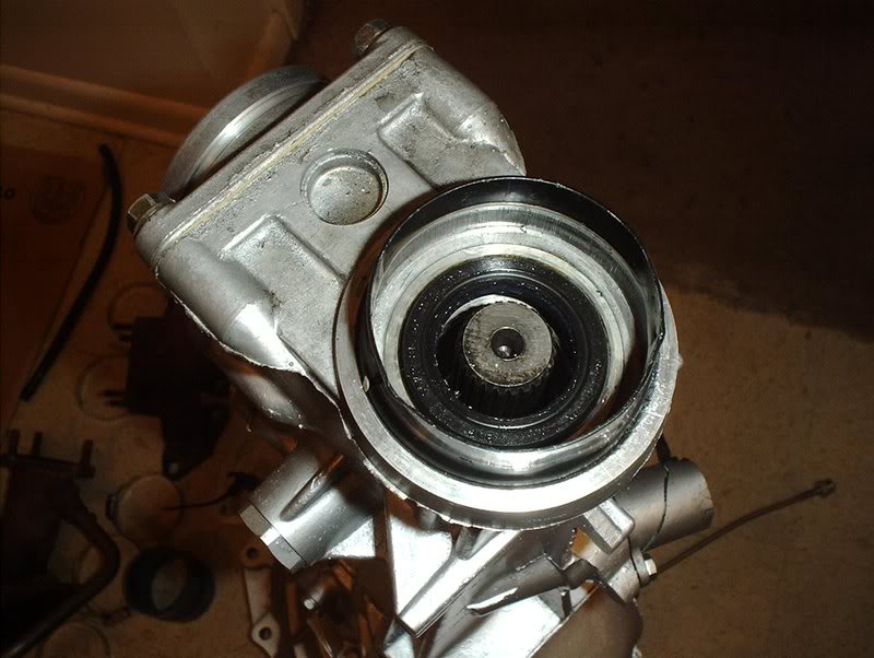
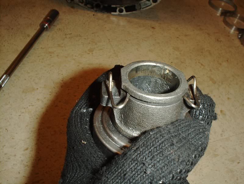
Lubed up the new seal with some gear oil and place it.
This is where your seal driver kit comes into play. I couldn't use it the regular way because the shaft was in the way...
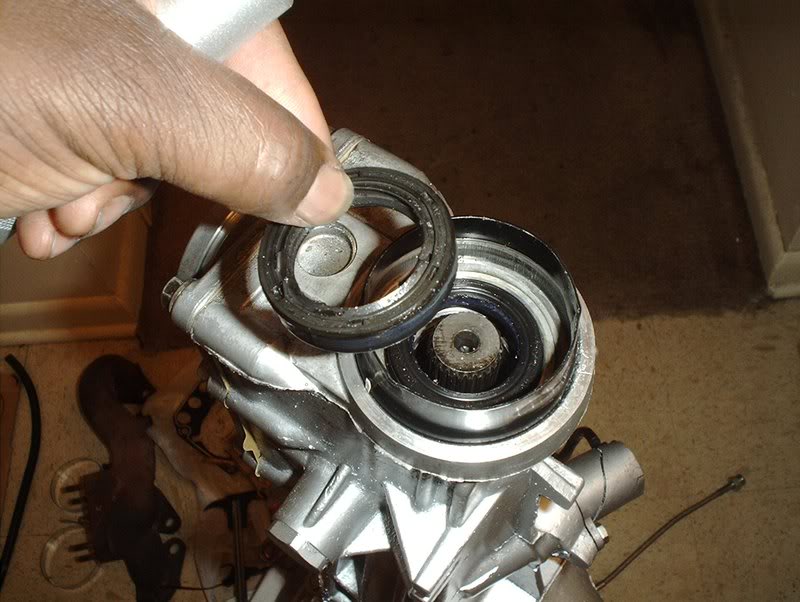
so I took the old seal and placed it on top of the new seal.
I took some of the drivers in the driver kit and placed them on top of the old seal and pushed down to seat the new tranny seal in.
Finished.
Tools needed:
Socket wrench
Socket extension
12mm socket
Seal puller
Seal driver
I started with the front transmission cover gasket. I was planning to swap out the front transmission seals also but I couldn't see any way to easily remove these seals without completely dissassembling the transmission and removing the shaft in order to gain access to them.
The seals under the front cover appear to be in perfect condition anyway so I just decided to roll the hard six and skip replacing them.
Front transmission cover gasket. Part#:32112-08U01
I removed the front cover earlier and as you can see it was quite filthy, covered in grease.
I got some Mean Green and a scrub brush, cleaned it up and regreased it. I hate handling dirty parts.
Start by taking the O-ring and putting it in place.
It will go here.
Take the O-ring...
and place it on the seal, it will stay in place when you put the front cover on.
Take a 12mm socket and replace the 5 bolts on the front cover. Torque them to 12-15ft.lbs.
Done.
Next, I replaced the gearbox gasket. Part#: 32516-03U11.
I pulled the old gasket off.
Use a razorblade to remove all traces of the old gasket.
Take the new gasket...
and place it on the underside of the gearbox cover...
and place it on the transmission.
Use a 12mm socket to replace the six bolts. Tighten them in a similar fashion to the valve cover bolts and torque to 10-13ft.lbs.
I also replaced the transmission rear seal.
Transmission rear seal. Part#: 32136-U0100.
Seal puller. Wish I had this when I did the front main oil seal.
Seal driver kit. This too!
Take your seal puller or you could use a prybar or flathead screwdriver and place it around the inside of the seal.
Like so.
Pull the old seal out.
Clean the area.
New seal and the old seal.
Lubed up the new seal with some gear oil and place it.
This is where your seal driver kit comes into play. I couldn't use it the regular way because the shaft was in the way...
so I took the old seal and placed it on top of the new seal.
I took some of the drivers in the driver kit and placed them on top of the old seal and pushed down to seat the new tranny seal in.
Finished.
 05-13-2008, 04:00 PM
#167
Contributing Member
Thread Starter
Join Date: Sep 2002
Location: Starkville, MS.
Posts: 1,192
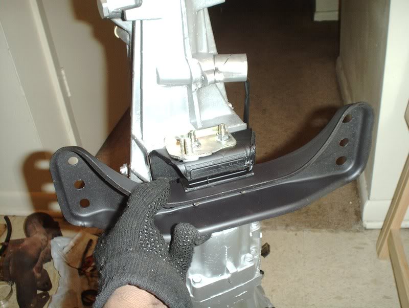
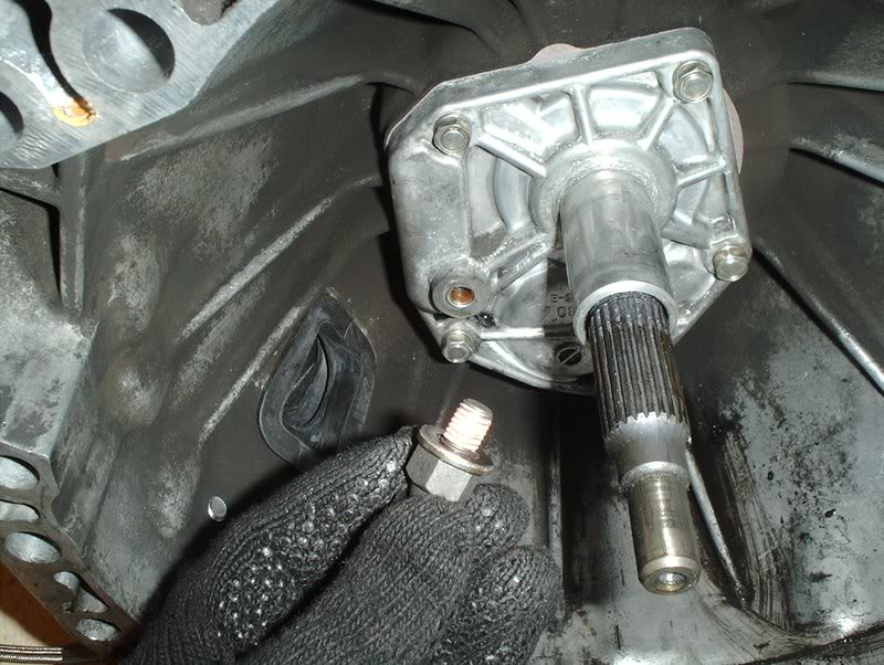
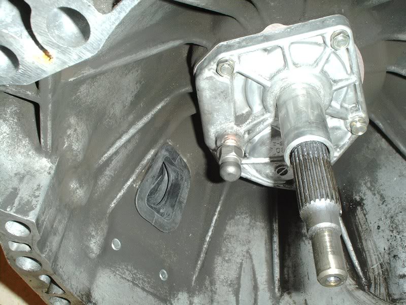
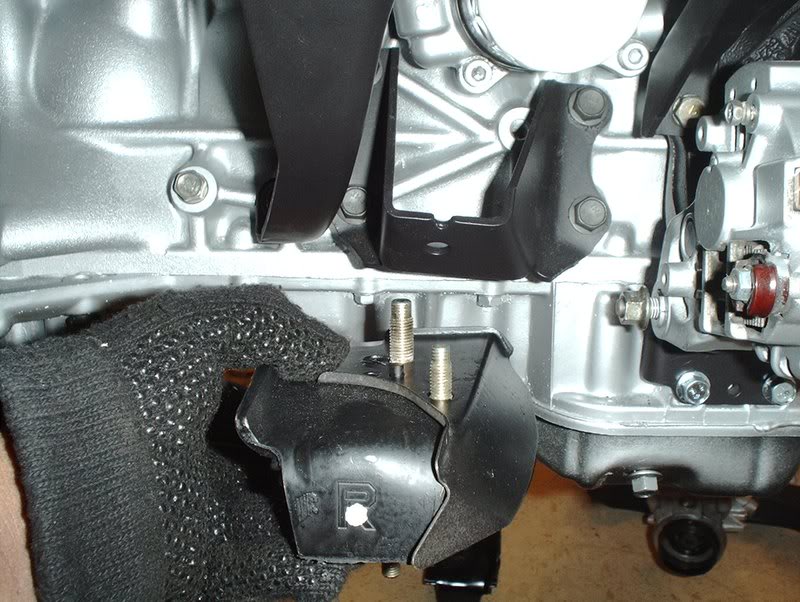
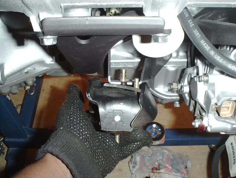
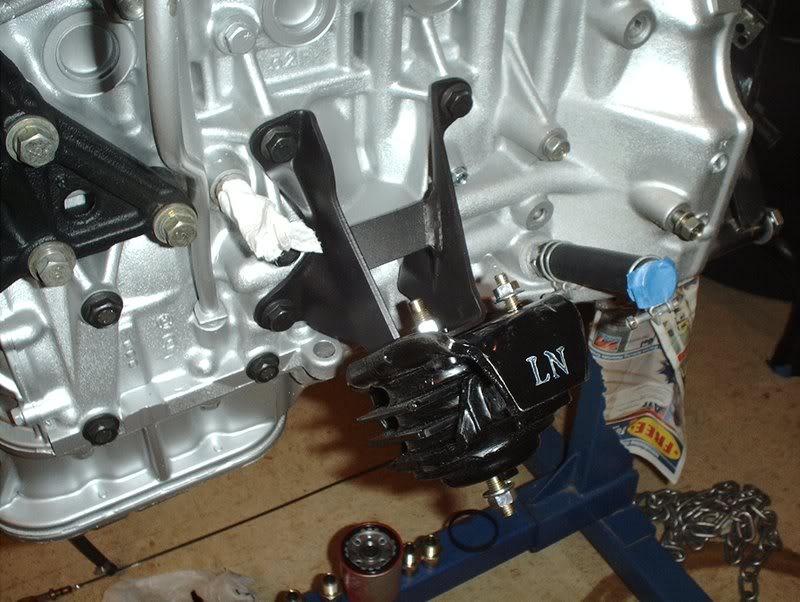
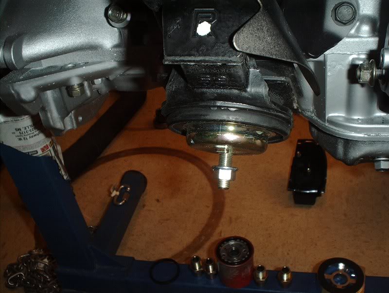
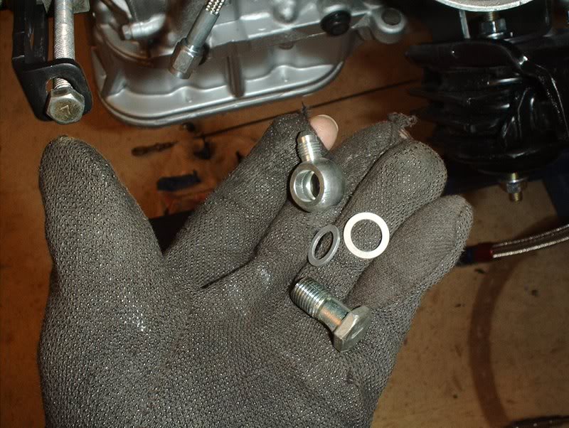
Transmission Mount
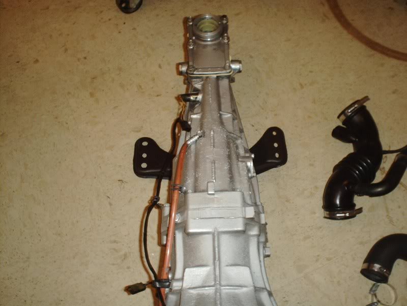
I also put the transmission mount and crossmember back on today.
Tools needed:
Socket wrench
Socket extension
12mm socket
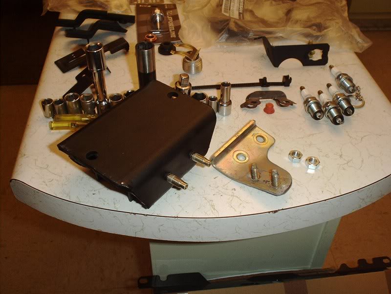
A transmission crossmember was the only thing my engine set was missing so I took the one off my KA, cleaned and prepped it.
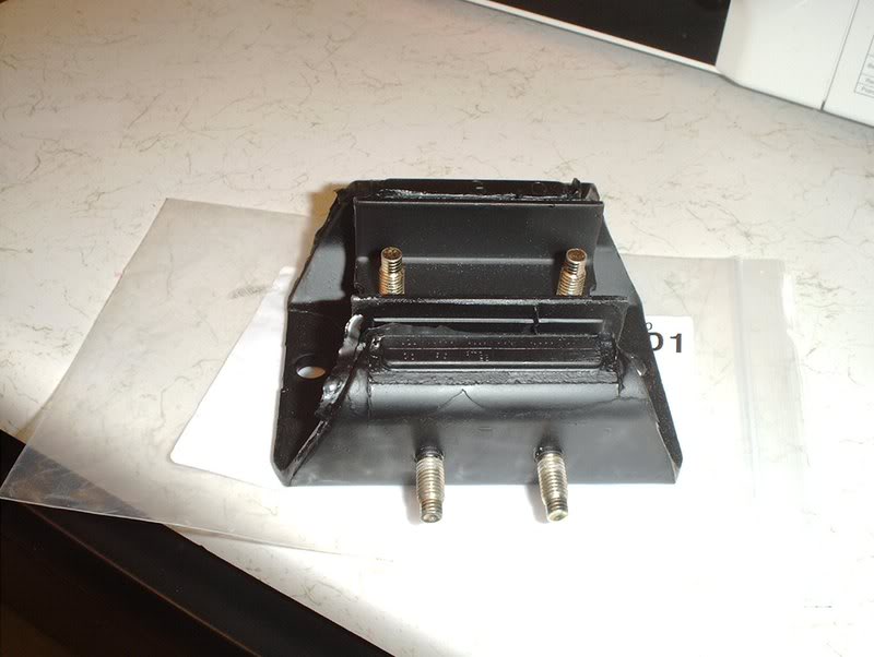
Nismo transmission mount. Part#:11320-RS541.
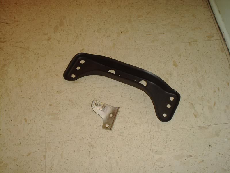
I'm still not sure what this bracket is for but I think it's for the exhaust. I can't remember what I unbolted from this when I pulled my KA.
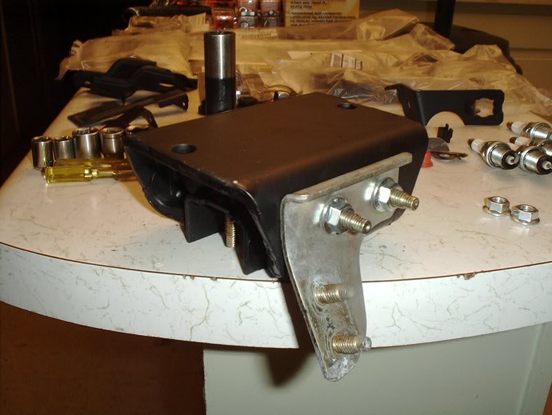
Bolt it back on with two nuts. Torque to 9-12ft.lbs. If you need replacements you can use M8-1,25. You can also use these for the engine mount heat shields.

Take that...
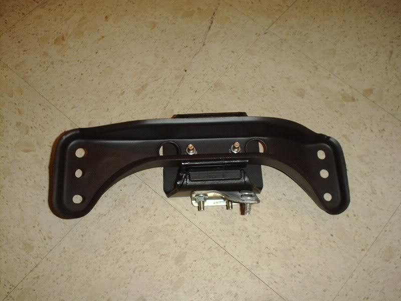
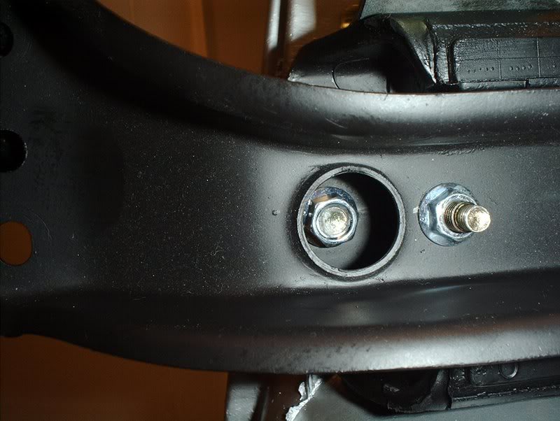
and bolt it to the transmission crossmember. Torque them to 16-21ft.lbs.
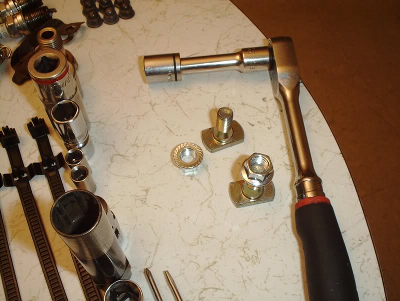
Next you'll need these bolts to mount the crossmember to the transmission, these gold bolts with the rectangular head. If you need replacements the part number is 11390-S13002. The nuts I just got at the parts store M10-1,25. You can also use them for the engine mounts.
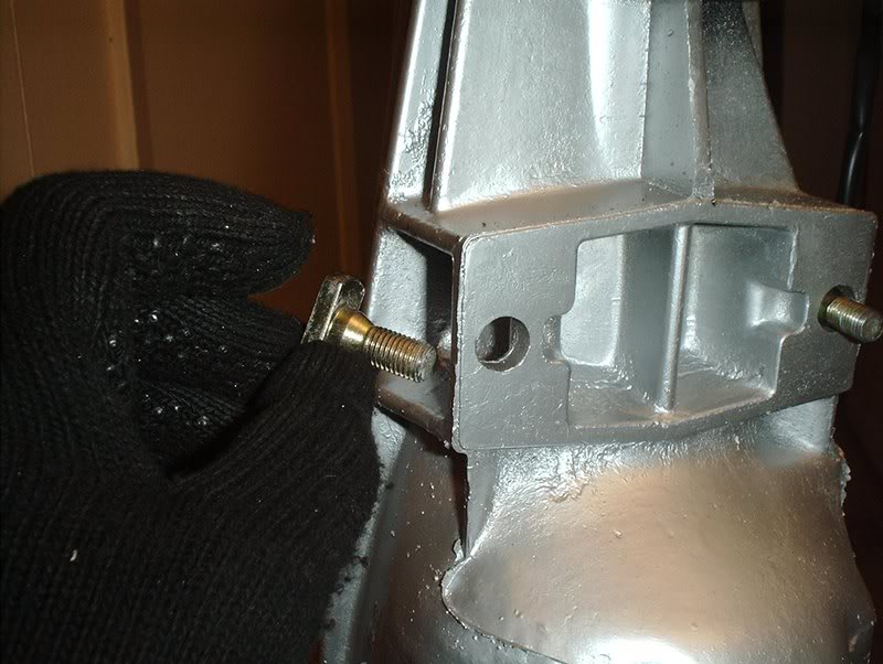
Take the crossmember bolts and place them here.
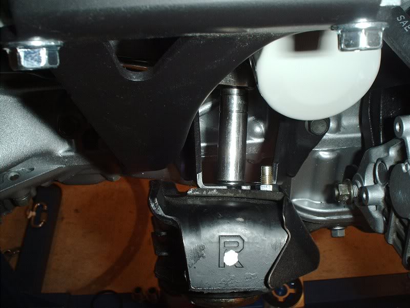
Put the crossmember into place...
thread the nuts and torque to 16-21ft.lbs.
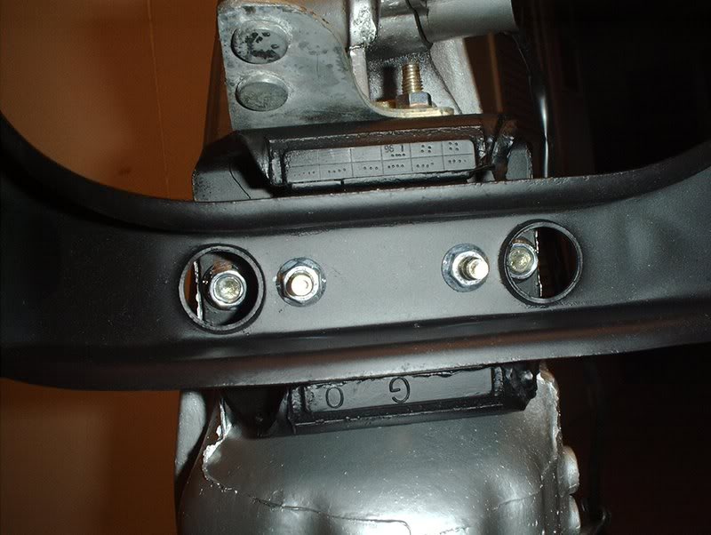
Complete!
Tools needed:
Socket wrench
Socket extension
12mm socket
A transmission crossmember was the only thing my engine set was missing so I took the one off my KA, cleaned and prepped it.
Nismo transmission mount. Part#:11320-RS541.
I'm still not sure what this bracket is for but I think it's for the exhaust. I can't remember what I unbolted from this when I pulled my KA.
Bolt it back on with two nuts. Torque to 9-12ft.lbs. If you need replacements you can use M8-1,25. You can also use these for the engine mount heat shields.
Take that...
and bolt it to the transmission crossmember. Torque them to 16-21ft.lbs.
Next you'll need these bolts to mount the crossmember to the transmission, these gold bolts with the rectangular head. If you need replacements the part number is 11390-S13002. The nuts I just got at the parts store M10-1,25. You can also use them for the engine mounts.
Take the crossmember bolts and place them here.
Put the crossmember into place...
thread the nuts and torque to 16-21ft.lbs.
Complete!
05-13-2008, 09:55 PM
#168
Contributing Member
Thread Starter
Join Date: Sep 2002
Location: Starkville, MS.
Posts: 1,192
Clutch Pivot Ball Install
I also got my clutch pivot ball in today.
Tools needed:
Socket wrench
Socket extension
17mm deepwell socket
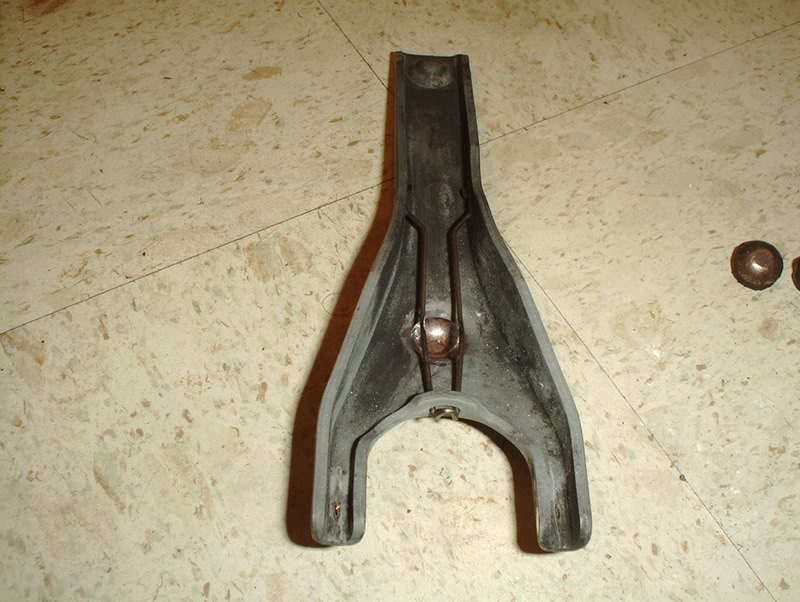
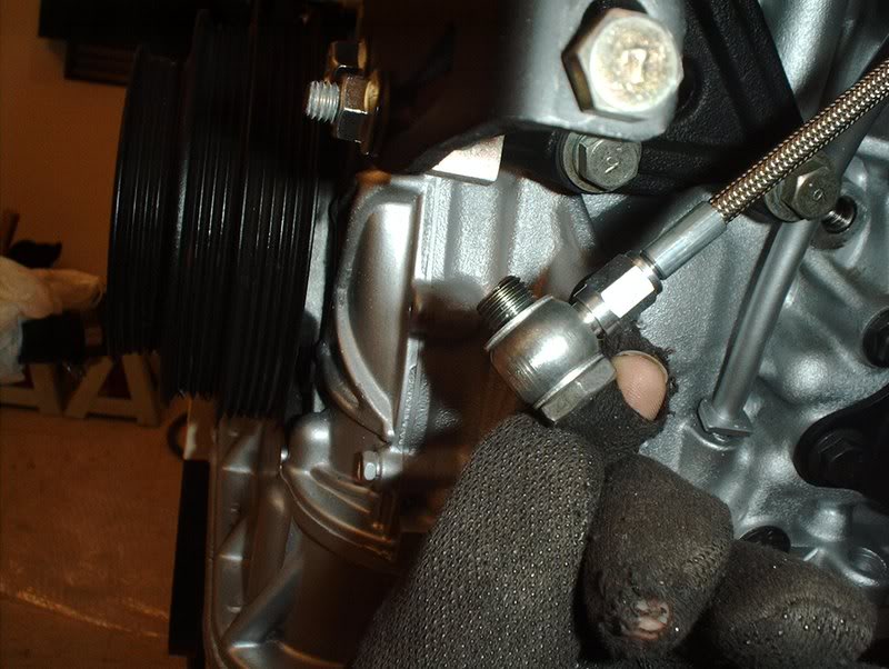
When I removed the clutch fork and throwout bearing the OEM pivot ball came apart so I decided to replace it with a new unit.
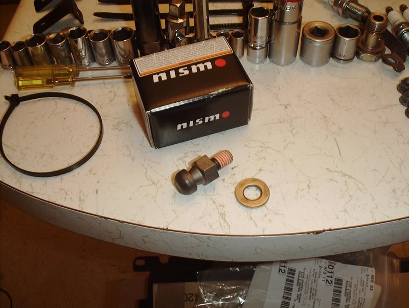
Nismo clutch pivot ball. Part#:30537-RS540.
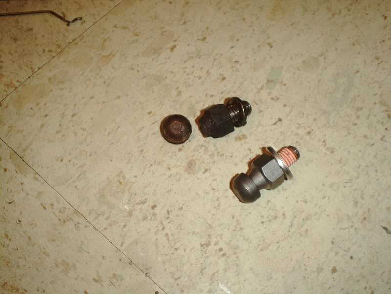
OEM clutch pivot vs. Nismo clutch pivot. My stock unit just split in two as you can see here.
Take the new pivot...
and thread it in.
Use the 17mm socket to tighten it.
Torque it to 14-25ft.lbs. and you're done.
While I was at it I played around with putting my clutch fork and throwout bearing back together. I couldn't exactly remember how everything fit together.
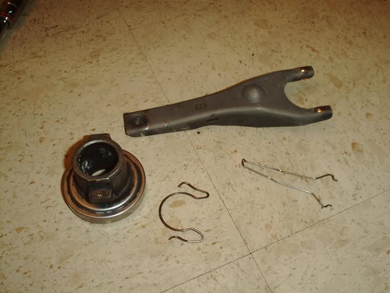
Clutch fork, throwout bearing, retainer spring and holder spring.
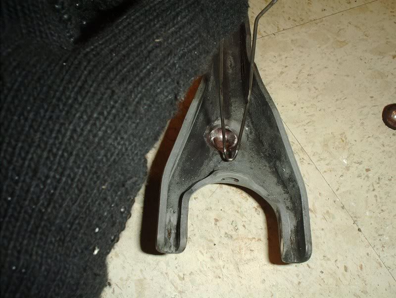
Take the clutch fork and the retainer spring...
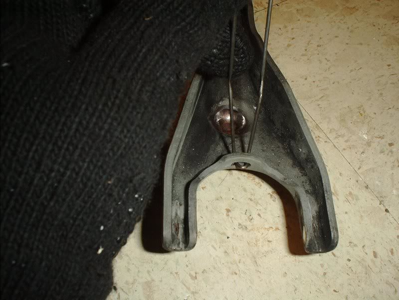
insert the tip like so in the slot on the clutch fork...
and the ends into the slits on the side of the clutch fork.
Take the throwout bearing/release bearing and insert the holder spring in the sides.
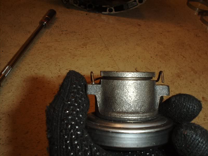

Slide the fork onto the throwout/release bearing and this is how it is connected.
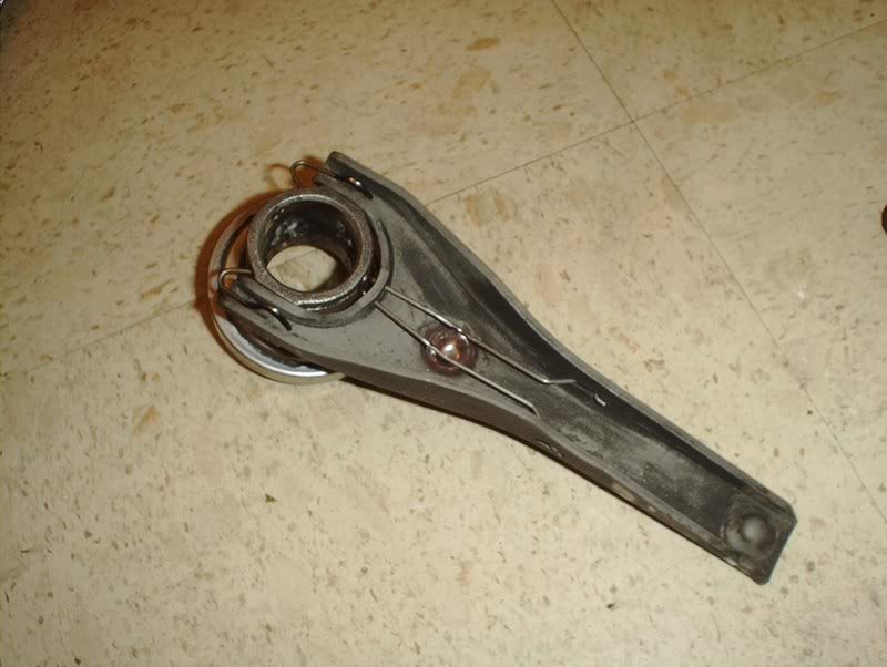
Of course it will be different when you actually put it on the tranny.
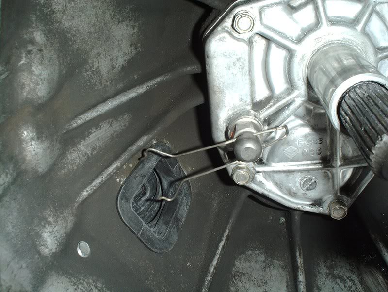
The retainer spring will be around the ball of the pivot ball...
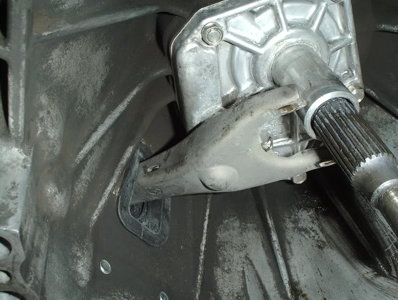
and the end of the clutch fork goes through the rubber boot on the side of the transmission and makes contact with the clutch slave cylinder.
Tools needed:
Socket wrench
Socket extension
17mm deepwell socket
When I removed the clutch fork and throwout bearing the OEM pivot ball came apart so I decided to replace it with a new unit.
Nismo clutch pivot ball. Part#:30537-RS540.
OEM clutch pivot vs. Nismo clutch pivot. My stock unit just split in two as you can see here.
Take the new pivot...
and thread it in.
Use the 17mm socket to tighten it.
Torque it to 14-25ft.lbs. and you're done.
While I was at it I played around with putting my clutch fork and throwout bearing back together. I couldn't exactly remember how everything fit together.
Clutch fork, throwout bearing, retainer spring and holder spring.
Take the clutch fork and the retainer spring...
insert the tip like so in the slot on the clutch fork...
and the ends into the slits on the side of the clutch fork.
Take the throwout bearing/release bearing and insert the holder spring in the sides.
Slide the fork onto the throwout/release bearing and this is how it is connected.
Of course it will be different when you actually put it on the tranny.
The retainer spring will be around the ball of the pivot ball...
and the end of the clutch fork goes through the rubber boot on the side of the transmission and makes contact with the clutch slave cylinder.
05-29-2008, 07:02 AM
#169
Contributing Member
Thread Starter
Join Date: Sep 2002
Location: Starkville, MS.
Posts: 1,192
Turbo Continued....
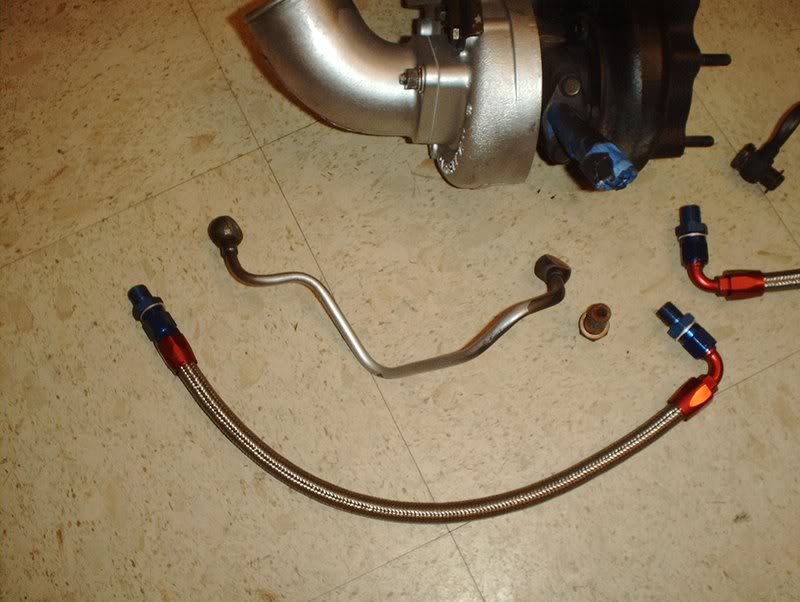
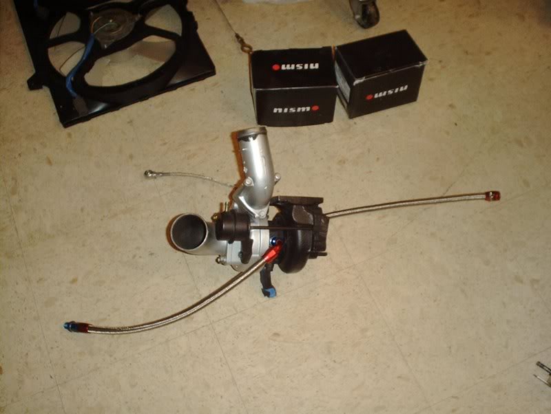
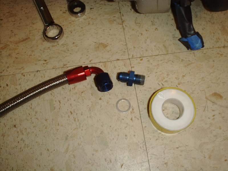
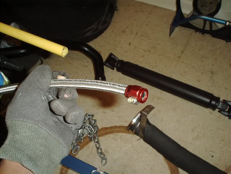
I got some stainless steel turbo lines in to replace the stock hardlines with.
Tools needed:
Socket wrench
15mm deepwell socket
18mm socket
19mm deepwell socket
12mm line wrench
Breaker bar
Torque wrench
Hammer
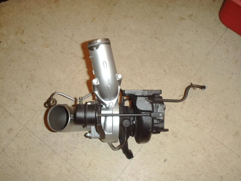
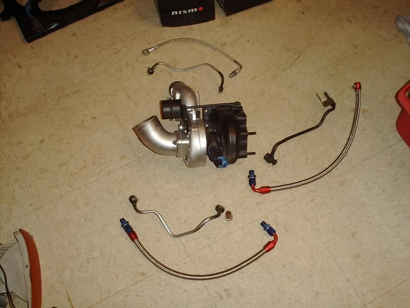
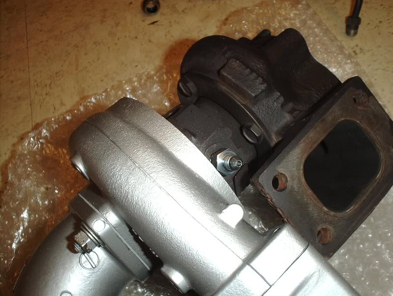
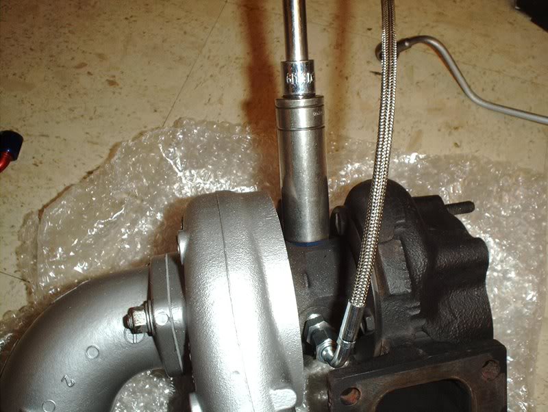
T25 Turbo
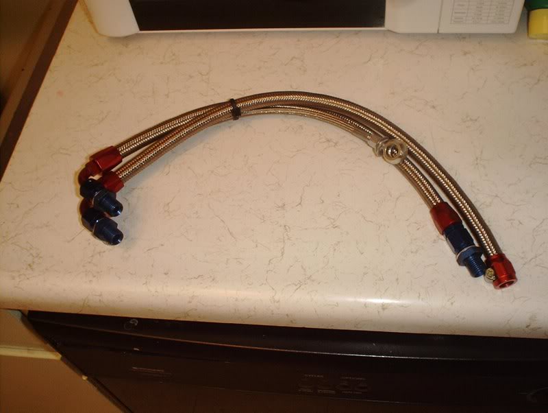
Circuit Sports Stainless Steel Turbo Lines
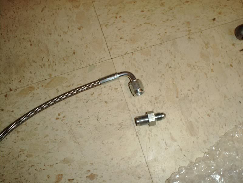
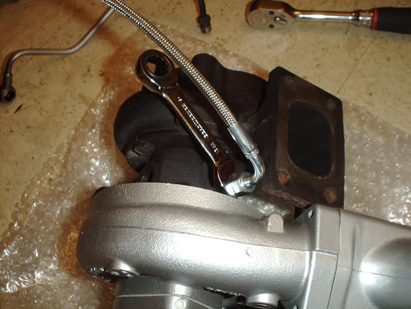
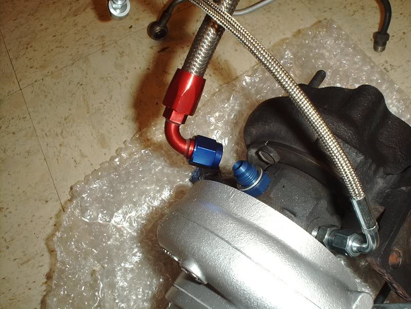
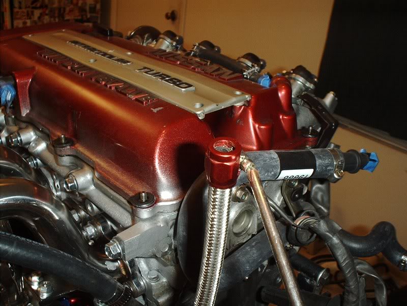
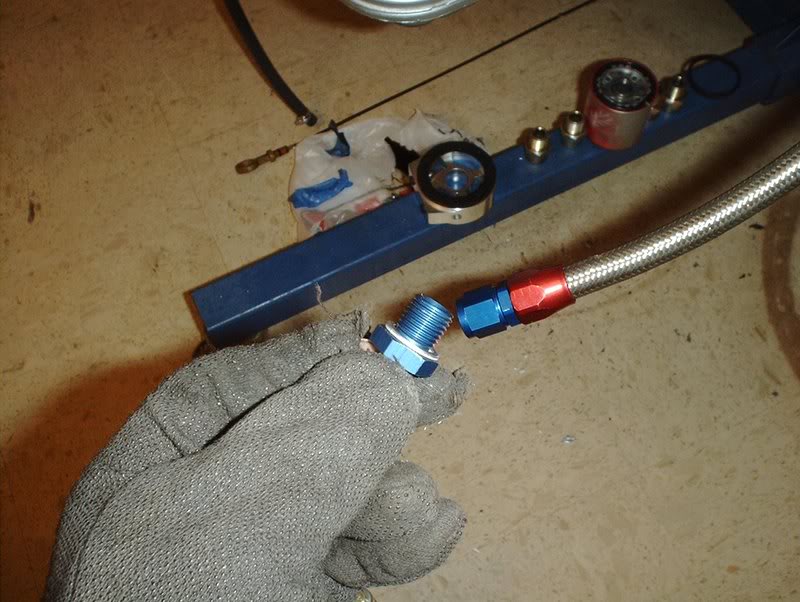
The top left line is the water inlet line, the top right line is the water return line and the bottom line is the oil inlet line.
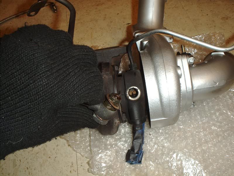
I started with the oil inlet line.
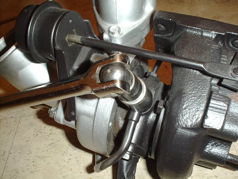
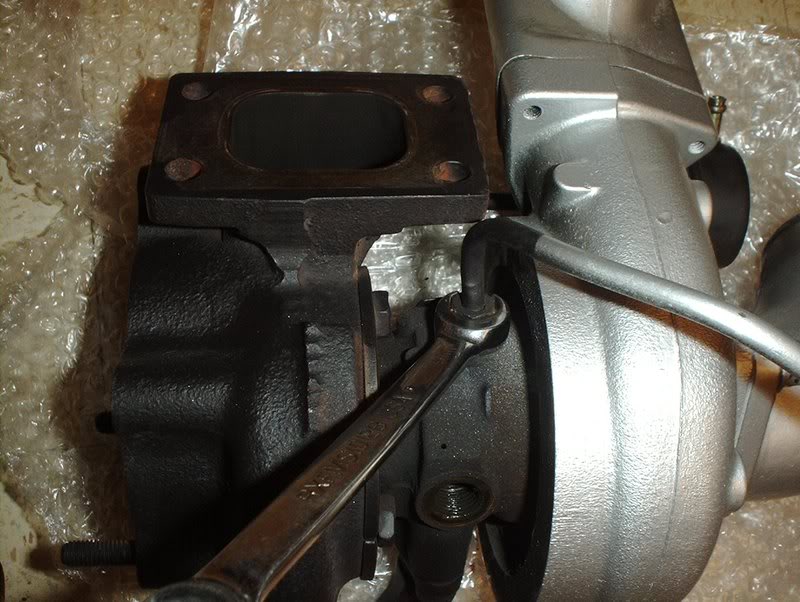
Use a 18mm socket with a breaker bar to remove the banjo bolt for the oil inlet line.
After I busted the banjo bolt loose I just used a socket wrench to remove the banjo from the turbo.
Off. You'll notice that there are two washers on either side of the banjo, I have a question about that later.
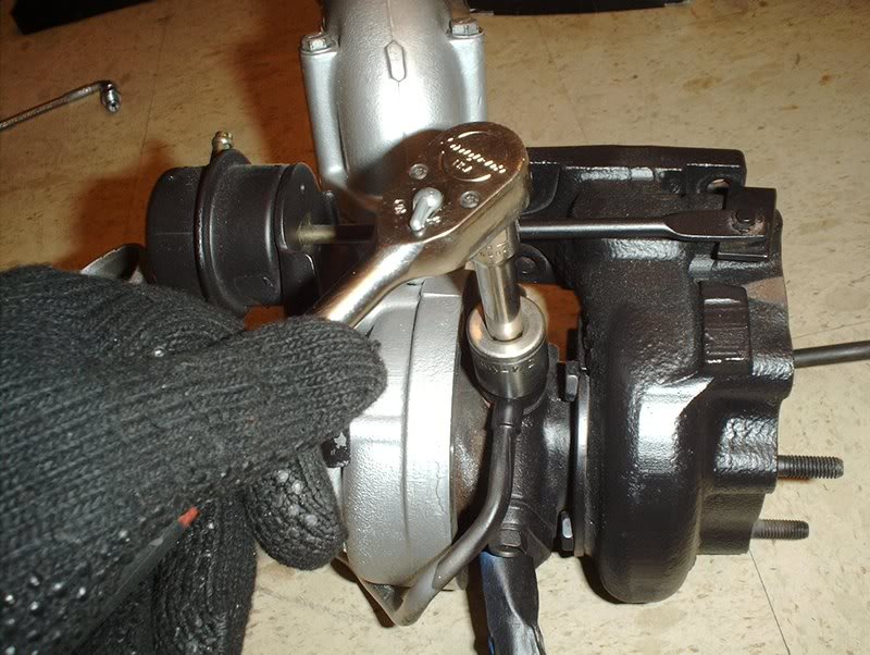
Flip the turbo over to move to the next set of lines. You'll need a line wrench to get the water return line off but you have to get the water inlet line off first to get to it.
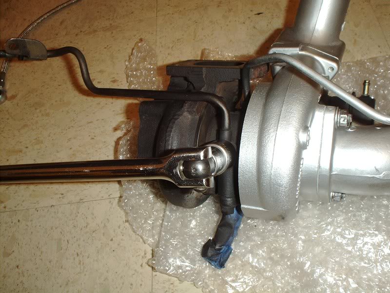
Use the same 18mm socket to remove the banjo bolt on the water inlet line.
Off.
Line wrench.
I took a line wrench for the water return line...
placed it around the line like so...
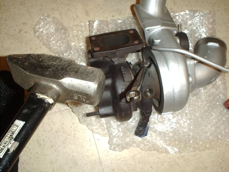
and since I couldn't crank it off by hand I used a hammer to tap it one time to bust it loose.
Like so.
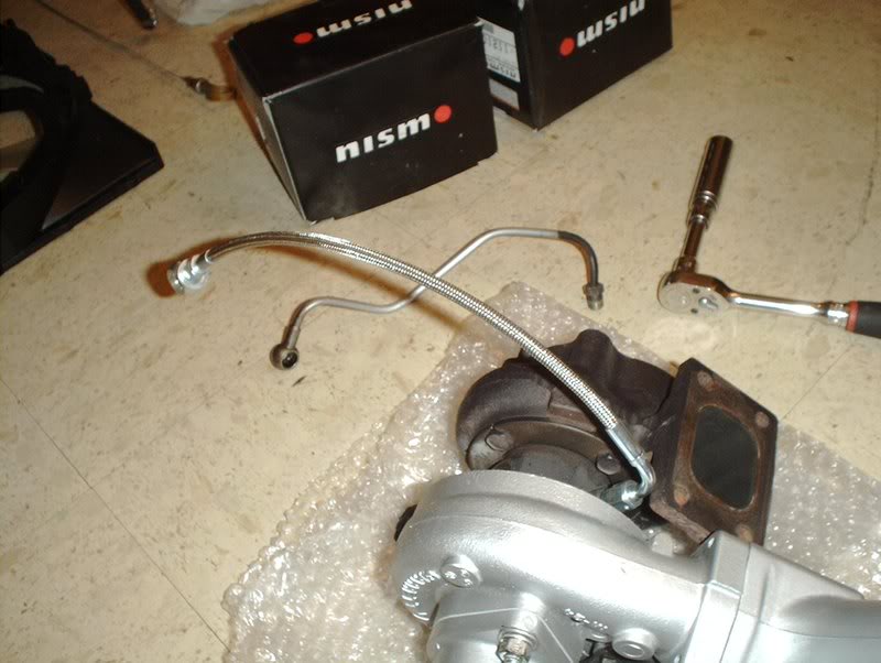
Lines off next to their counterparts.
Oil inlet lines.
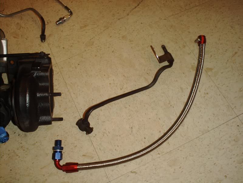
Water inlet lines.
Water return lines.
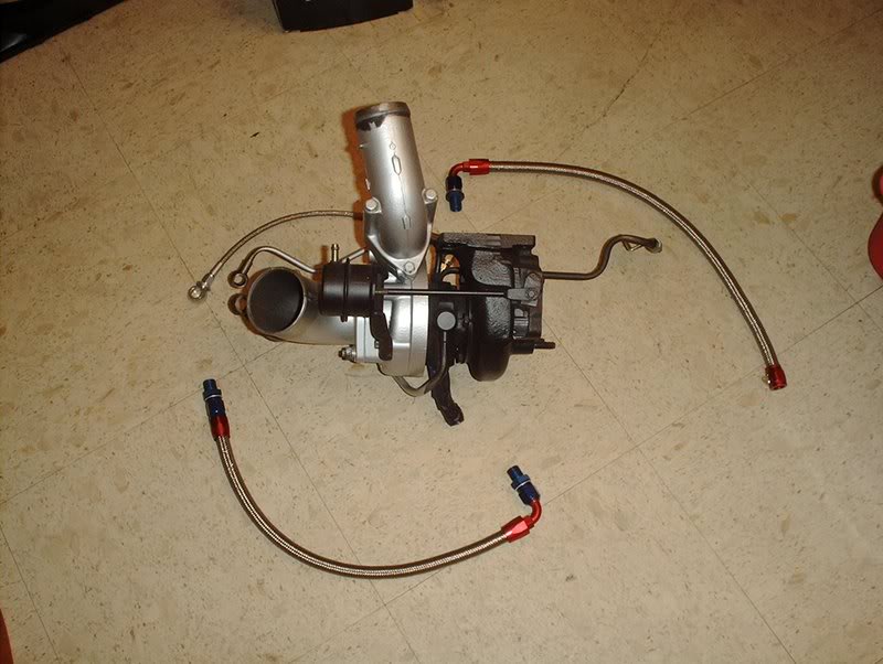
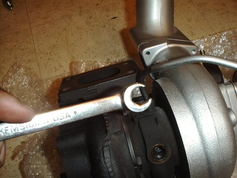
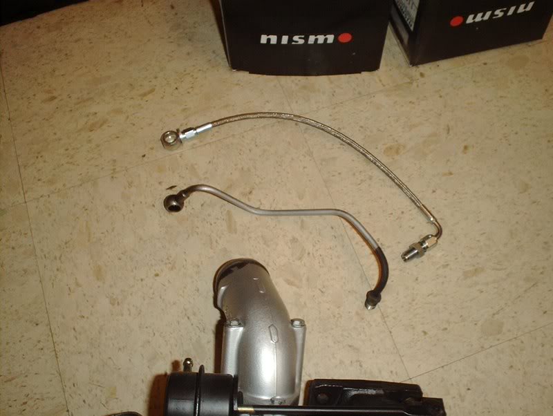
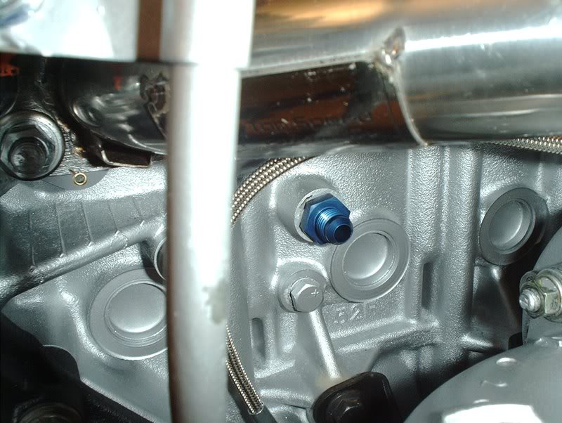
I started with the water return line.
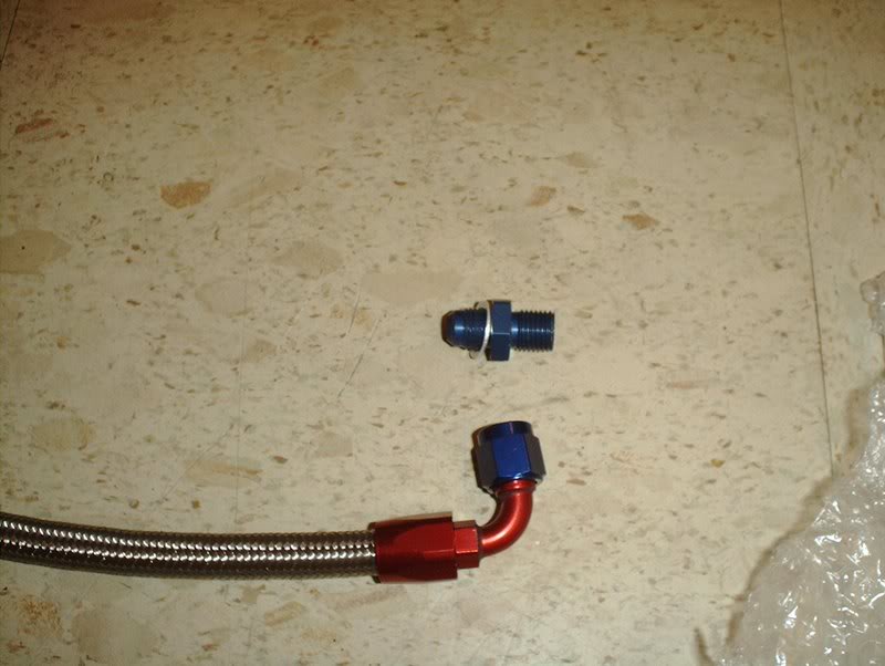
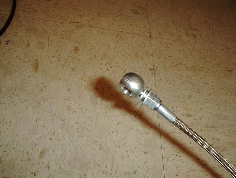
I don't know if this is the way to do this but it seemed easier to get these lines on by taking the fittings off the line...
threading them in the turbo by hand...
and using a socket to tighten them. I used a 15mm deepwell socket here so it would fit over the fitting. The fitting gets torqued to 14-23ft.lbs.
I placed the line on the fitting...
and used a 13mm wrench to tighten the line onto the fitting.
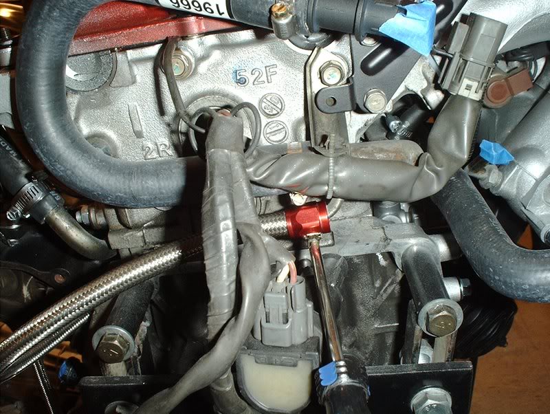
Water return line complete.
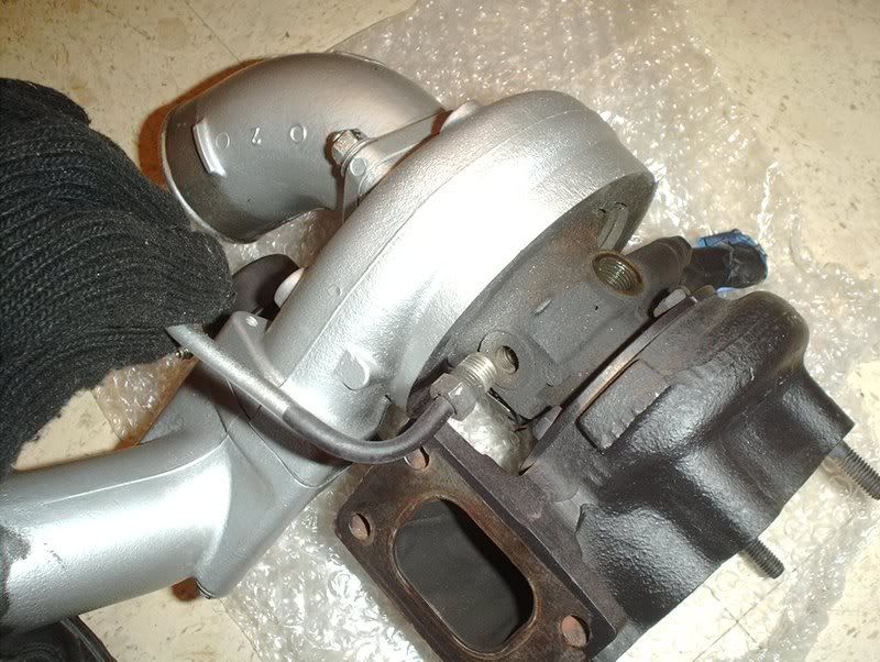
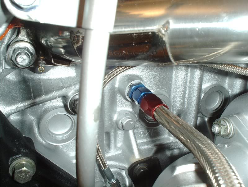
Next, I moved on to the water inlet line.
I took the fitting off.
I threaded the fitting in by hand.
I used a 19mm deepwell socket to tighten it, it also gets torqued to 14-23ft.lbs.
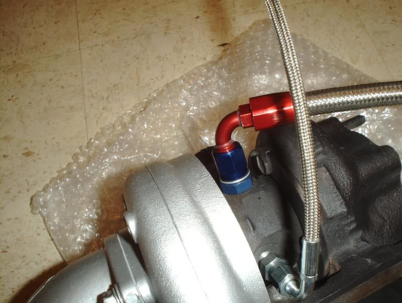
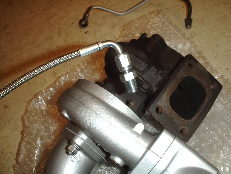
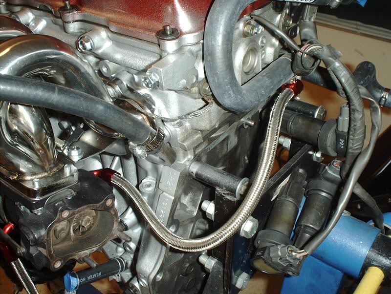
Place the line on and use a 19mm wrench to tighten it down.
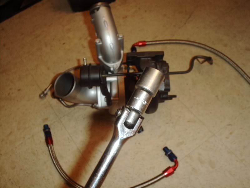
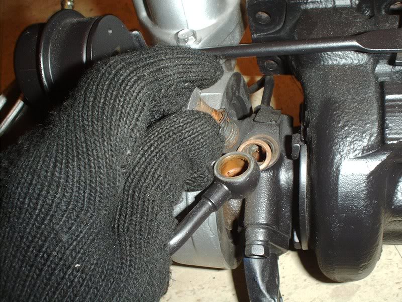
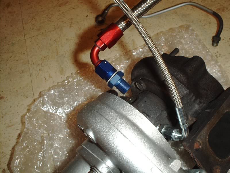
Finally, I moved to the oil inlet line.
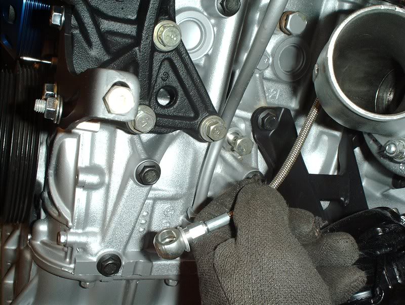
Remove the fitting...
Place it on like so and use a 19mm deepwell socket to tighten and torque to 14-23ft.lbs.
Place the line on and use a 19mm wrench to tighten.
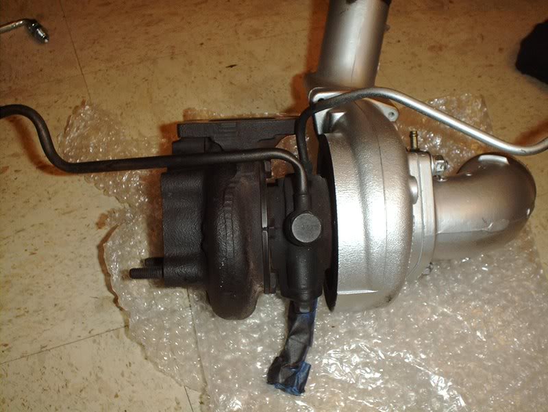
Complete!
TO BE CONTINUED........
QUESTION TIME
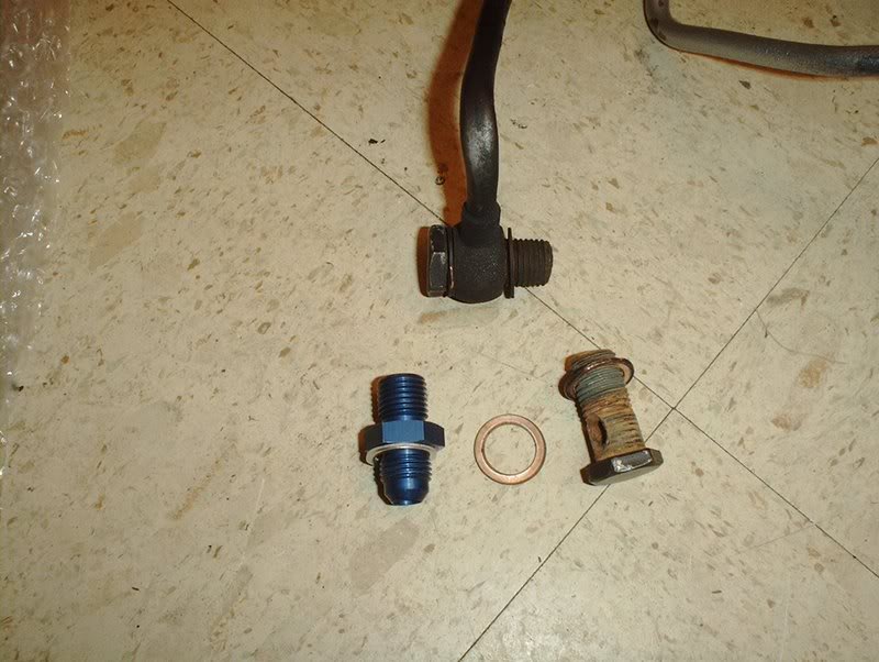
The stainless steel lines have a fitting that come with only one washer on one side of the fitting while the OEM banjo bolts have two washers on either sides so should I use one of the banjo bolt washers so that the new lines have washers on both sides when they get bolted to the turbo?????
Tools needed:
Socket wrench
15mm deepwell socket
18mm socket
19mm deepwell socket
12mm line wrench
Breaker bar
Torque wrench
Hammer
T25 Turbo
Circuit Sports Stainless Steel Turbo Lines
The top left line is the water inlet line, the top right line is the water return line and the bottom line is the oil inlet line.
I started with the oil inlet line.
Use a 18mm socket with a breaker bar to remove the banjo bolt for the oil inlet line.
After I busted the banjo bolt loose I just used a socket wrench to remove the banjo from the turbo.
Off. You'll notice that there are two washers on either side of the banjo, I have a question about that later.
Flip the turbo over to move to the next set of lines. You'll need a line wrench to get the water return line off but you have to get the water inlet line off first to get to it.
Use the same 18mm socket to remove the banjo bolt on the water inlet line.
Off.
Line wrench.
I took a line wrench for the water return line...
placed it around the line like so...
and since I couldn't crank it off by hand I used a hammer to tap it one time to bust it loose.
Like so.
Lines off next to their counterparts.
Oil inlet lines.
Water inlet lines.
Water return lines.
I started with the water return line.
I don't know if this is the way to do this but it seemed easier to get these lines on by taking the fittings off the line...
threading them in the turbo by hand...
and using a socket to tighten them. I used a 15mm deepwell socket here so it would fit over the fitting. The fitting gets torqued to 14-23ft.lbs.
I placed the line on the fitting...
and used a 13mm wrench to tighten the line onto the fitting.
Water return line complete.
Next, I moved on to the water inlet line.
I took the fitting off.
I threaded the fitting in by hand.
I used a 19mm deepwell socket to tighten it, it also gets torqued to 14-23ft.lbs.
Place the line on and use a 19mm wrench to tighten it down.
Finally, I moved to the oil inlet line.
Remove the fitting...
Place it on like so and use a 19mm deepwell socket to tighten and torque to 14-23ft.lbs.
Place the line on and use a 19mm wrench to tighten.
Complete!
TO BE CONTINUED........
QUESTION TIME
The stainless steel lines have a fitting that come with only one washer on one side of the fitting while the OEM banjo bolts have two washers on either sides so should I use one of the banjo bolt washers so that the new lines have washers on both sides when they get bolted to the turbo?????
Last edited by positron; 05-29-2008 at 07:09 AM.
05-29-2008, 07:21 AM
#170
Contributing Member
Thread Starter
Join Date: Sep 2002
Location: Starkville, MS.
Posts: 1,192
Tranmission Drain Plug
I also swapped out my transmission drain plug with a magnetic transmission drain plug.
Tools needed:
Socket wrench
Socket extension
3/8 socket adapter
A rag
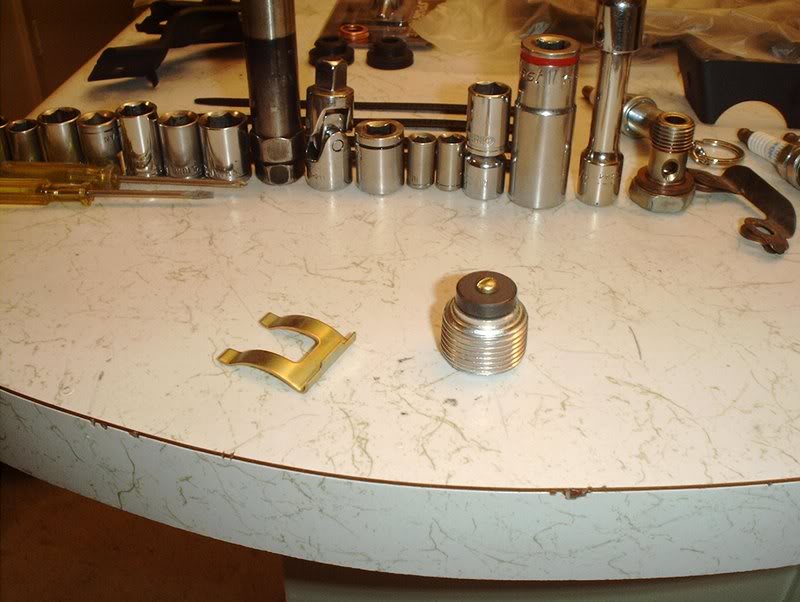
OEM magnetic drain plug part#:32103-U840A
It's basically serves the same purpose as a magnetic oil drain plug by collecting any metal particles in your transmission fluid.
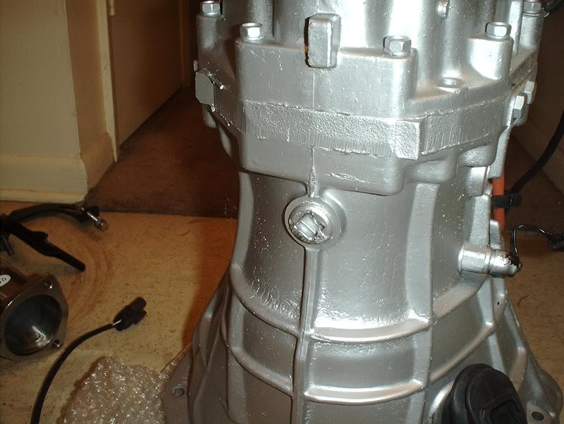
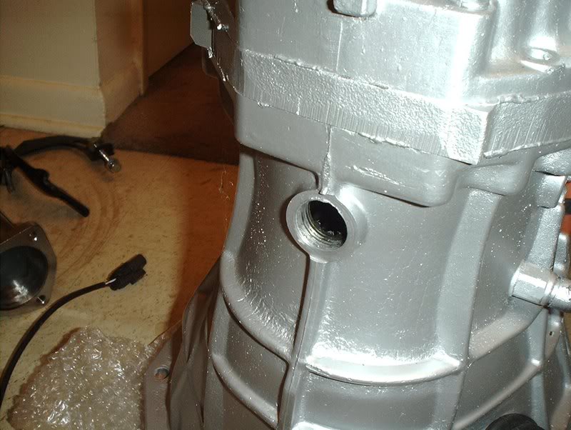
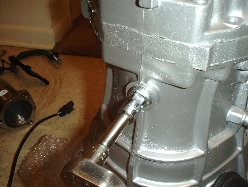
Get access to the tranny drain plug on the bottom of the transmission.
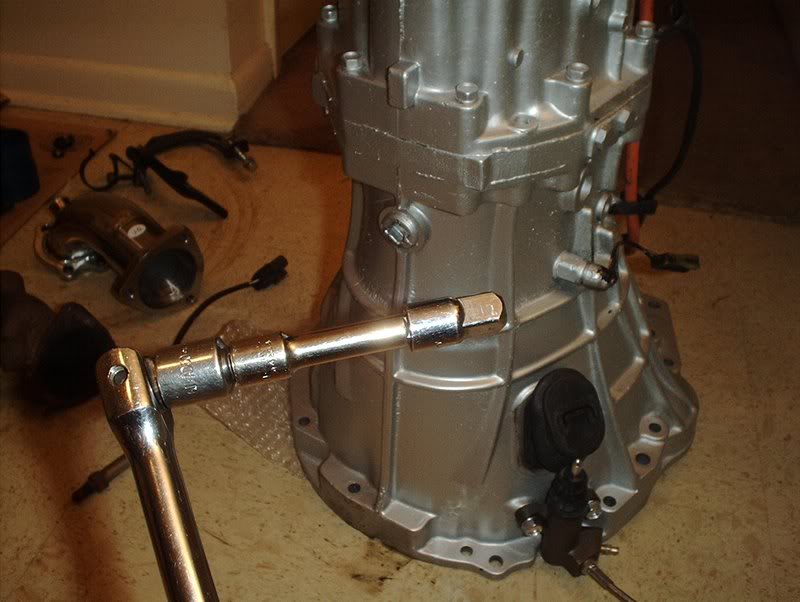
Use a socket extension with a 3/8 adapter on it...
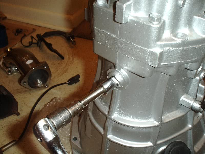
to remove the drain plug.
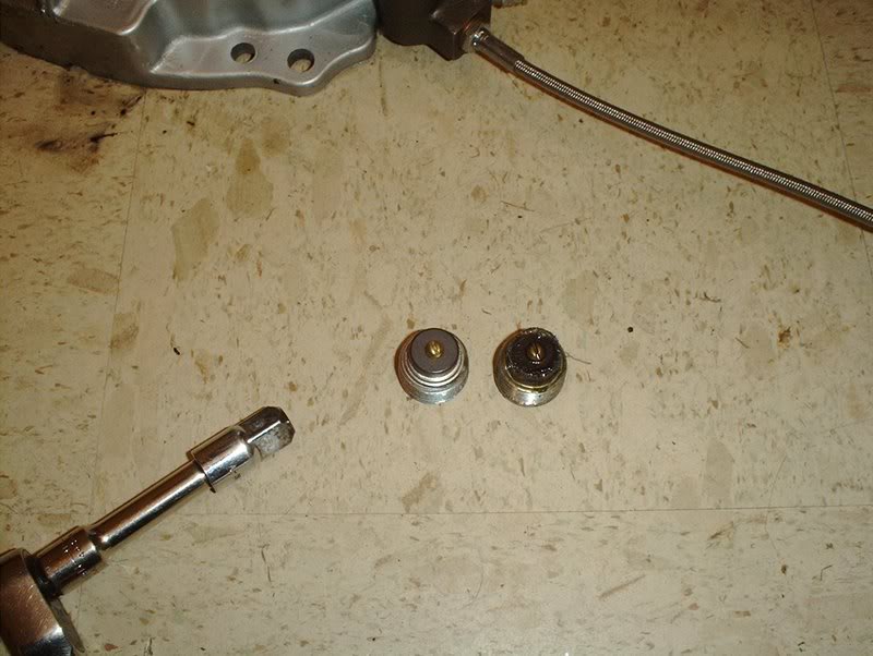
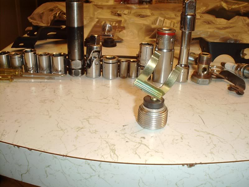
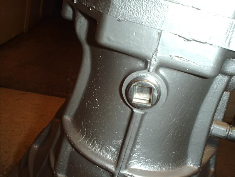
New plug vs. old plug.
Keep a rag or paper towel handy to wipe off any excess fluid still in the transmission that may leak out after you remove the drain plug.
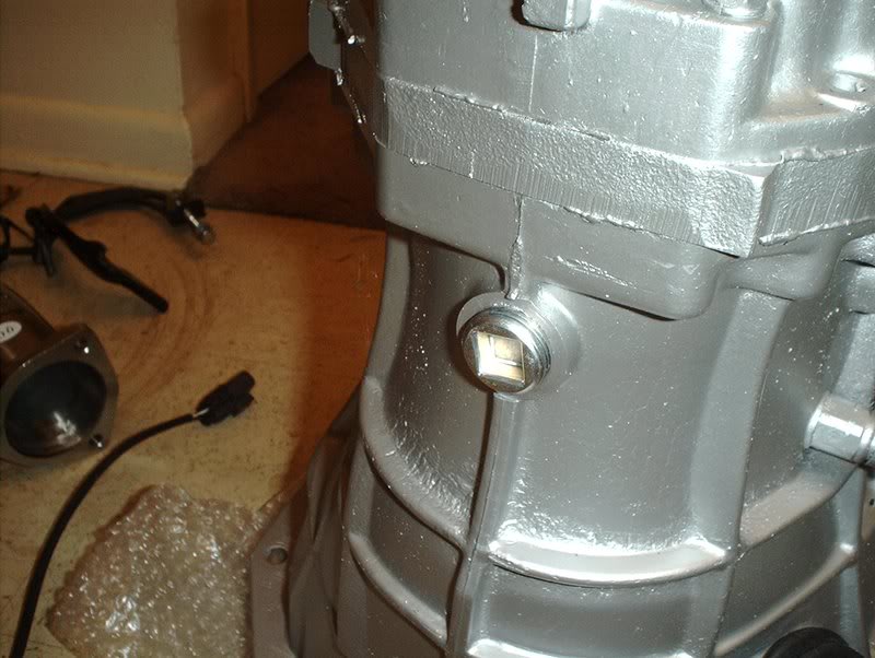
Place the new plug in.
Tighten and torque to 18-25ft.lbs.
"Something something something darkside....something something something complete!!!!"
Tools needed:
Socket wrench
Socket extension
3/8 socket adapter
A rag
OEM magnetic drain plug part#:32103-U840A
It's basically serves the same purpose as a magnetic oil drain plug by collecting any metal particles in your transmission fluid.
Get access to the tranny drain plug on the bottom of the transmission.
Use a socket extension with a 3/8 adapter on it...
to remove the drain plug.
New plug vs. old plug.
Keep a rag or paper towel handy to wipe off any excess fluid still in the transmission that may leak out after you remove the drain plug.
Place the new plug in.
Tighten and torque to 18-25ft.lbs.
"Something something something darkside....something something something complete!!!!"
Last edited by positron; 05-29-2008 at 07:23 AM.
05-31-2008, 04:20 AM
#171
Contributing Member
Thread Starter
Join Date: Sep 2002
Location: Starkville, MS.
Posts: 1,192
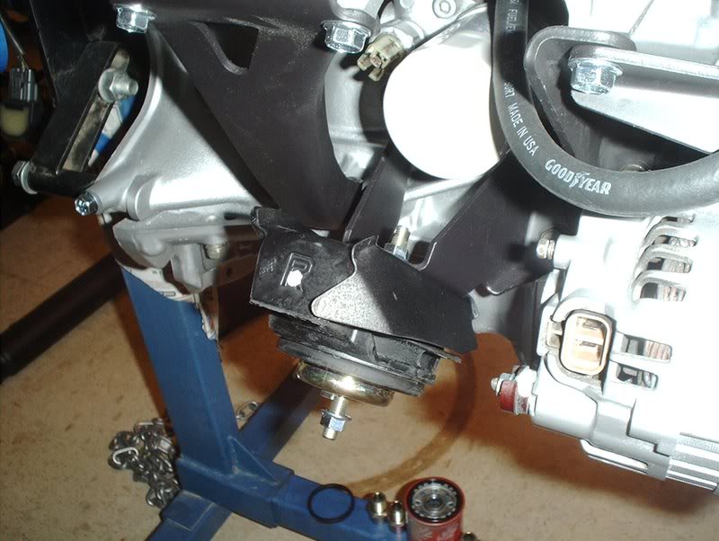
Motor/Engine Mounts
I got my motor mounts in today.
Tools needed:
Socket wrench
13mm socket
14mm deepwell socket
14mm wrench
Torque wrench
There are quite a few brands of motor mounts for the 240SX...
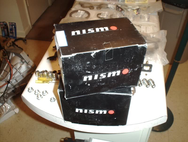
I went with the NISMO motor mounts.
Right mount part#:11210-RS540
Left mount part#:11220-RS540
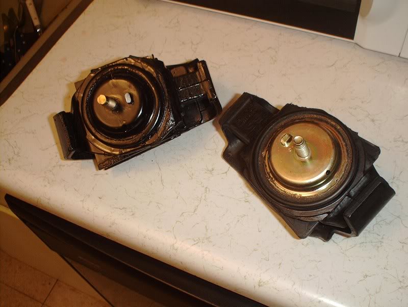
Don't forget your heatshields.
Take the heatshield...
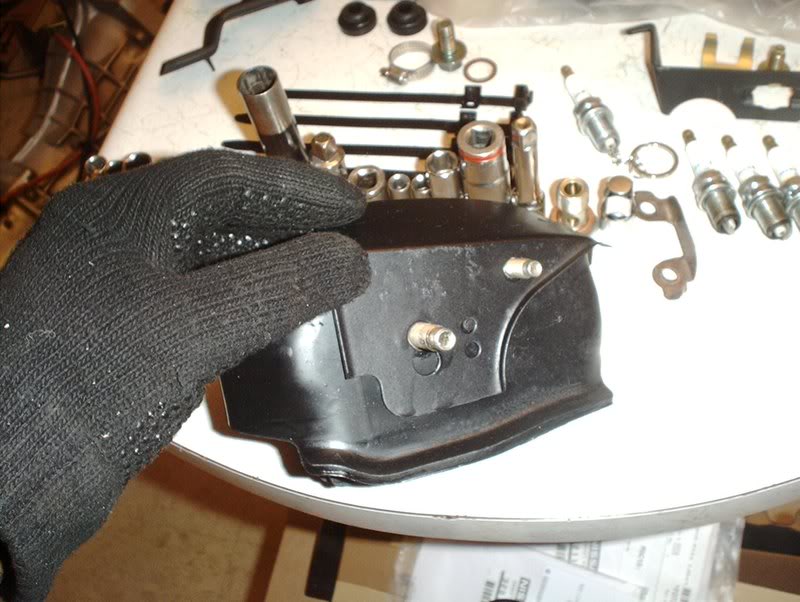
and place it on the mount like so.
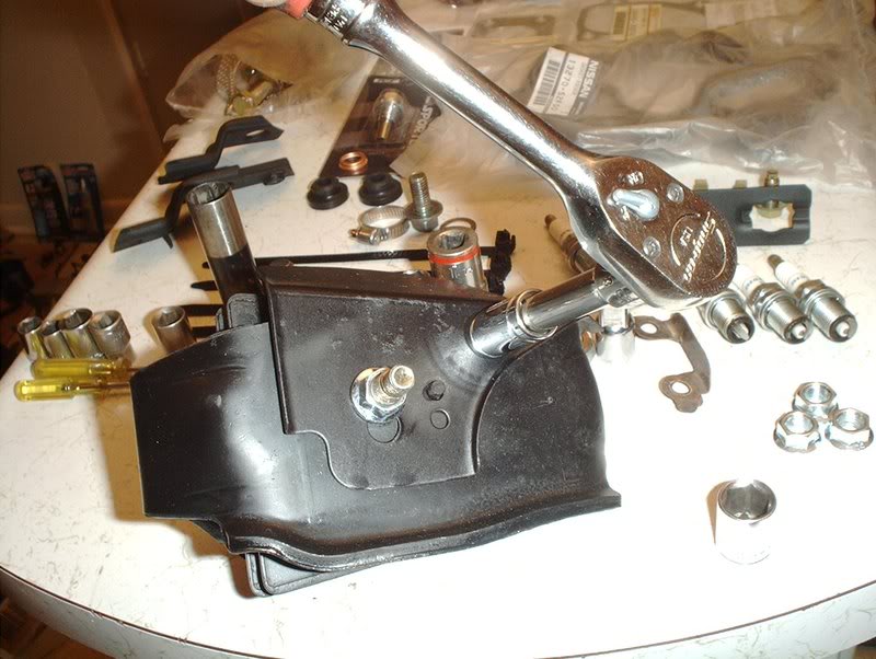
Use a 13mm socket to tighten and torque it to 16-21ft.lbs. If you need replacement nuts for the heatshields you can use M8-1,25 and for the the top and bottom motor mount nuts you can use M10-1,25. Don't put the motor mount nut on yet, that's just for show, you can't put the mount on the brackets with the nut on them.
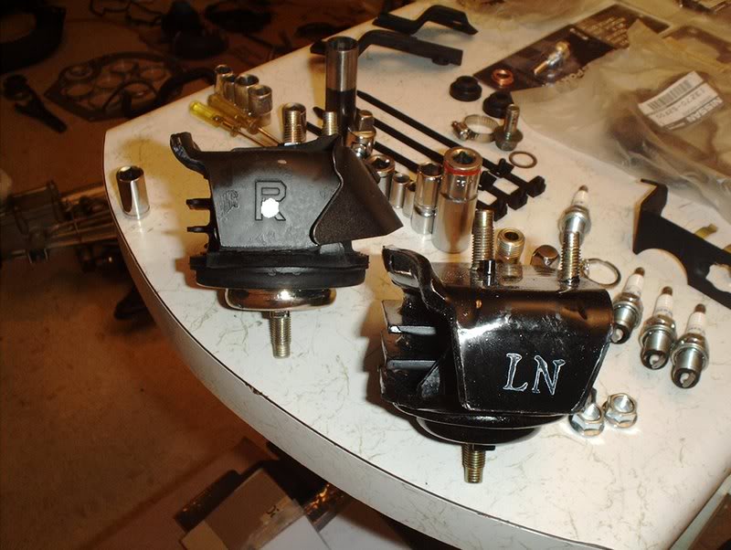
The mounts are clearly marked with a "L" for left and a "R" for right.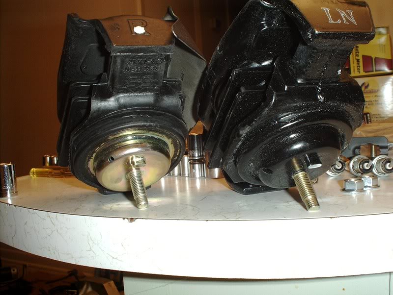
But if for some reason yours aren't, the gold one goes on the passenger side while the black one goes on the drivers side.
Take your mount...
and place it on the motor mount bracket.
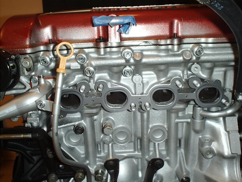
You'll need a deepwell 14mm socket here to tighten the mount to the bracket and torque to 32-41ft.lbs. You can also use a 14mm wrench to tighten them if need be because it gets kind of cramped on the intake side. You may need to remove that intake manifold bracket if it gets in your way when you go to torque this nut down.
Finished on the intake side...
and the exhaust side as well.
You can go ahead and place another M10-1,25 nut on the bottom of your mounts for the install but remember to remove it when it comes time to drop the motor in or you might have a bad day. When you do drop the motor in the bay these get torqued to 51-58ft.lbs.
Tools needed:
Socket wrench
13mm socket
14mm deepwell socket
14mm wrench
Torque wrench
There are quite a few brands of motor mounts for the 240SX...
I went with the NISMO motor mounts.
Right mount part#:11210-RS540
Left mount part#:11220-RS540
Don't forget your heatshields.
Take the heatshield...
and place it on the mount like so.
Use a 13mm socket to tighten and torque it to 16-21ft.lbs. If you need replacement nuts for the heatshields you can use M8-1,25 and for the the top and bottom motor mount nuts you can use M10-1,25. Don't put the motor mount nut on yet, that's just for show, you can't put the mount on the brackets with the nut on them.
The mounts are clearly marked with a "L" for left and a "R" for right.
But if for some reason yours aren't, the gold one goes on the passenger side while the black one goes on the drivers side.
Take your mount...
and place it on the motor mount bracket.
You'll need a deepwell 14mm socket here to tighten the mount to the bracket and torque to 32-41ft.lbs. You can also use a 14mm wrench to tighten them if need be because it gets kind of cramped on the intake side. You may need to remove that intake manifold bracket if it gets in your way when you go to torque this nut down.
Finished on the intake side...
and the exhaust side as well.
You can go ahead and place another M10-1,25 nut on the bottom of your mounts for the install but remember to remove it when it comes time to drop the motor in or you might have a bad day. When you do drop the motor in the bay these get torqued to 51-58ft.lbs.
05-31-2008, 11:58 AM
#172
Contributing Member
Thread Starter
Join Date: Sep 2002
Location: Starkville, MS.
Posts: 1,192
Turbo Lines Continued....
I went back and re-did my turbo lines based on some good information from a forum member and a mechanic.
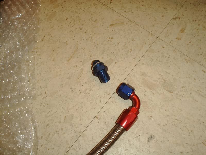
Before, I had decided to use the supplied washers and get an extra set from the parts store so I could have crush washers on both sides of the lines but I found out some useful information.
"The crush washer is used to seal the fittings going into the turbo center section. The lines all have AN fittings on their ends, which seal on the 37* flare, so you don't need to put the washers between the fittings and the lines. Put them between the fittings and the turbo."
This made since as I was wondering why they would only supply half of the washers that you would need to put these lines on, turns out they do supply the right amount of washers you just need to know where to use them.
I hadn't pad attention earlier but they even provide two new washers for the water inlet line.
You should apply some teflon tape to the fitting to turbo side and I learned something new from a mechanic about applying teflon tape that I didn't know...
you apply the teflon tape in the opposite direction of the way that the bolt/fitting is going to be threaded...you learn something new everyday!
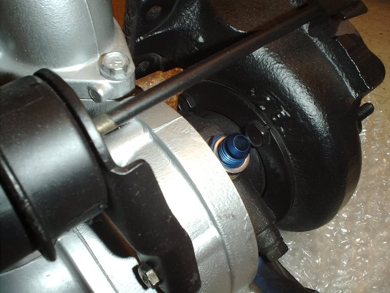
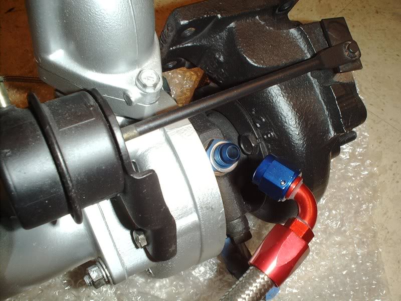
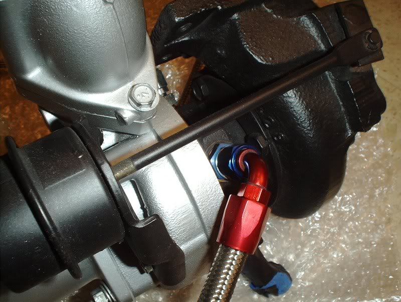
Tighten and re-torque the fittings down and you are done. Also, no crush washer is needed on the smaller water inlet to turbo fitting because it's has a AN fitting on that end as well.
Before, I had decided to use the supplied washers and get an extra set from the parts store so I could have crush washers on both sides of the lines but I found out some useful information.
"The crush washer is used to seal the fittings going into the turbo center section. The lines all have AN fittings on their ends, which seal on the 37* flare, so you don't need to put the washers between the fittings and the lines. Put them between the fittings and the turbo."
This made since as I was wondering why they would only supply half of the washers that you would need to put these lines on, turns out they do supply the right amount of washers you just need to know where to use them.
I hadn't pad attention earlier but they even provide two new washers for the water inlet line.
You should apply some teflon tape to the fitting to turbo side and I learned something new from a mechanic about applying teflon tape that I didn't know...
you apply the teflon tape in the opposite direction of the way that the bolt/fitting is going to be threaded...you learn something new everyday!
Tighten and re-torque the fittings down and you are done. Also, no crush washer is needed on the smaller water inlet to turbo fitting because it's has a AN fitting on that end as well.
 05-31-2008, 03:42 PM
#174
Contributing Member
Thread Starter
Join Date: Sep 2002
Location: Starkville, MS.
Posts: 1,192
There should have been a set on the original engine's mounts. A new set is like $8 a piece http://www.courtesyparts.com/betasit...1420_1425.html
06-01-2008, 05:20 AM
#175
Registered User

Join Date: Oct 2007
Location: Manahawkin, NJ
Posts: 48
Looks great as usual. However the lines on the turbo that you're calling water are oil, and the lines you're calling oil are water. The oil is fed into the top of the turbo and drains downward into the pan. The water is pumped in one side and out the other, doesn't matter the direction. Otherwise, great work.
Oh yeah, make sure you grease the heck out of the from plate on the trans where the throwout bearing slides.
Oh yeah, make sure you grease the heck out of the from plate on the trans where the throwout bearing slides.
06-02-2008, 12:59 AM
#176
Contributing Member
Thread Starter
Join Date: Sep 2002
Location: Starkville, MS.
Posts: 1,192
Looks great as usual. However the lines on the turbo that you're calling water are oil, and the lines you're calling oil are water. The oil is fed into the top of the turbo and drains downward into the pan. The water is pumped in one side and out the other, doesn't matter the direction. Otherwise, great work.
Oh yeah, make sure you grease the heck out of the from plate on the trans where the throwout bearing slides.
Oh yeah, make sure you grease the heck out of the from plate on the trans where the throwout bearing slides.
 06-13-2008, 10:52 AM
#177
Contributing Member
Thread Starter
Join Date: Sep 2002
Location: Starkville, MS.
Posts: 1,192
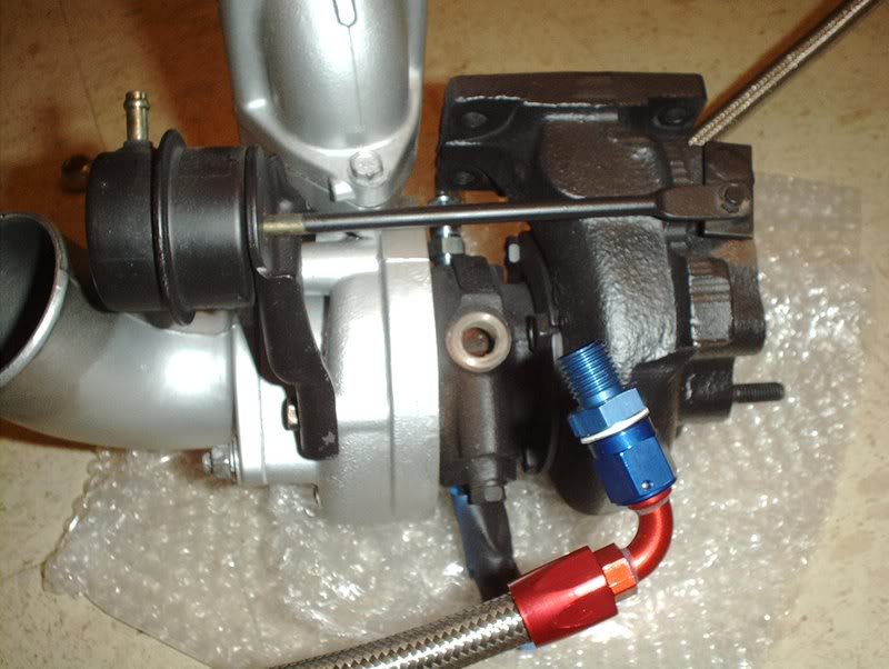
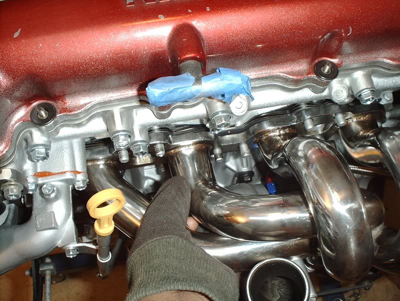
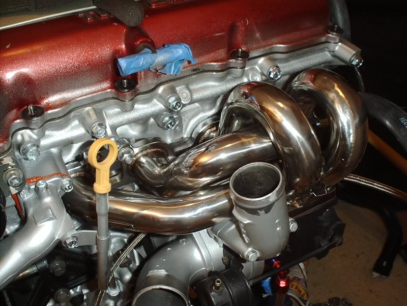
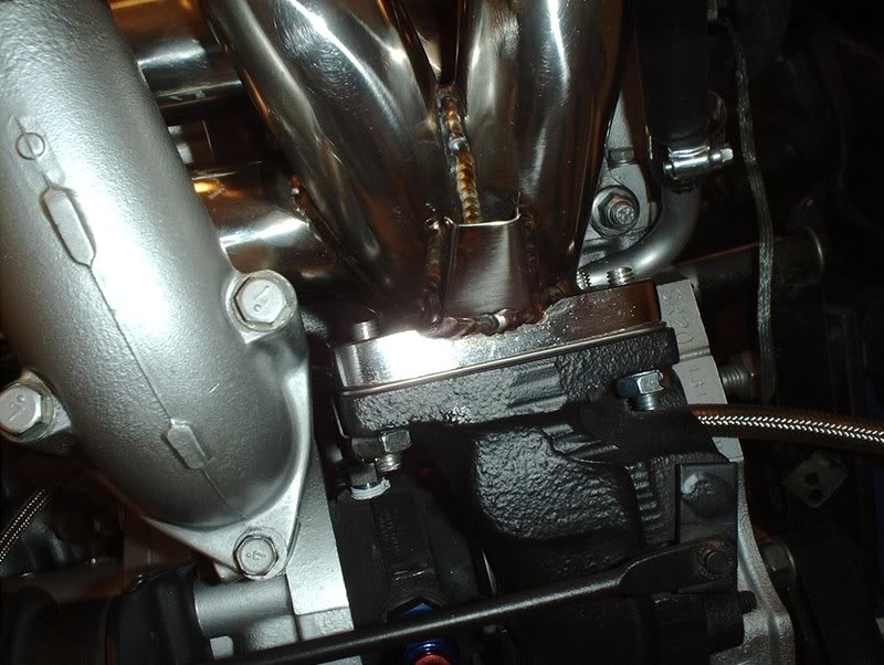
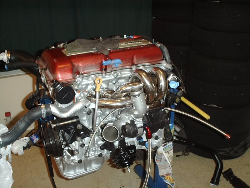
Turbo Manifold/Outlet Install
I finally got a exhaust manifold and turbo outlet. I did some research and narrowed my decision to a Tomei Extreme manifold and Circuit Sports outlet but decided to scrap those plans and get those items when I upgrade to a new T28 and go front mount. For the stock turbo I just went with the best "bang for the buck" setup.
Tools needed:
Socket wrench
Socket extension
13mm socket
14mm socket
15mm socket
Needlenose pliers
Screwdriver
Hammer(you'll see why later)
Anti-seize
Threadlocker
Razorblade
I got a setup in the other day.
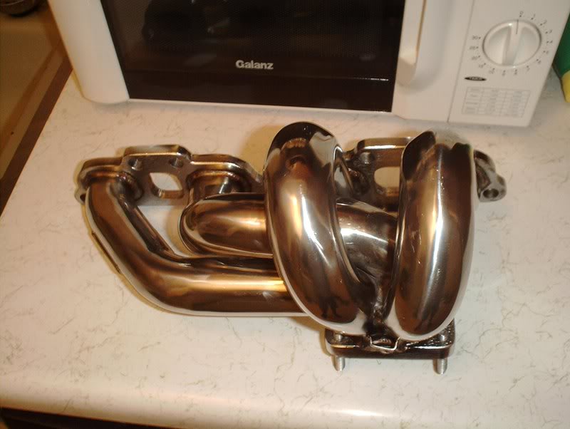
Megan Racing turbo manifold.
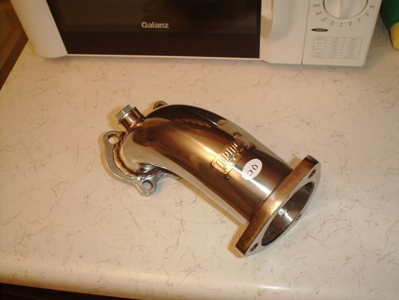
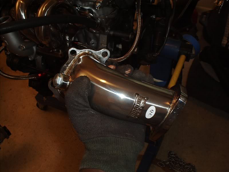
Megan Racing turbo outlet.
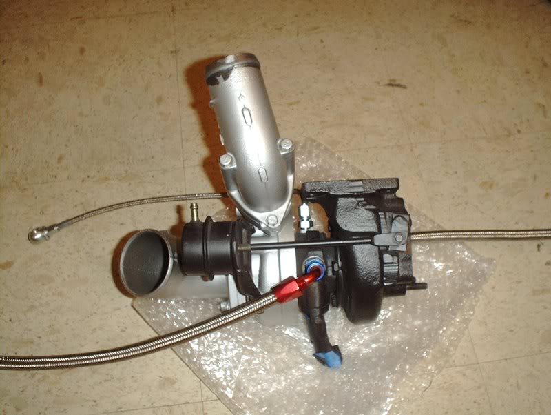
OEM T25 S13 Turbo
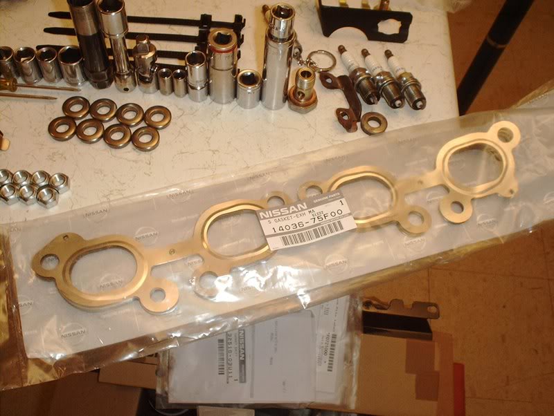
OEM multilayer metal exhaust manifold gasket part#:14036-75F00.
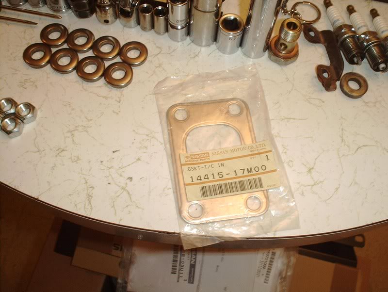
OEM metal turbo inlet gasket part#:14415-17M00.
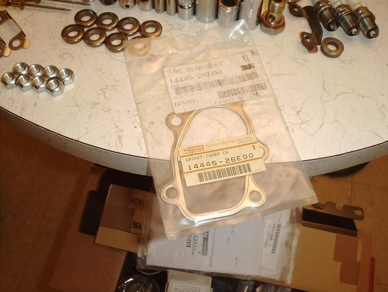
OEM metal turbo outlet gasket part#:14445-26E00.
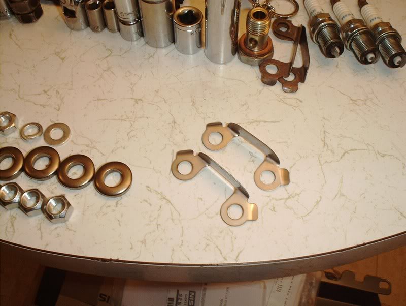
OEM turbo locking plates part#:14495-40P10.
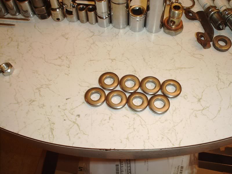
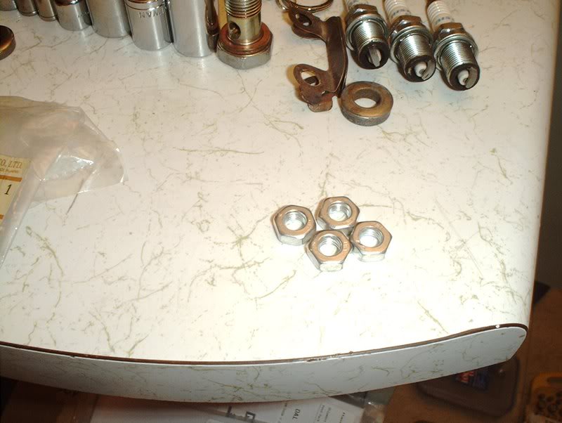
OEM exhaust manifold washer part#:14037-42L02.
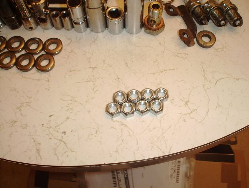
OEM exhaust manifold nut part#:08912-8401A
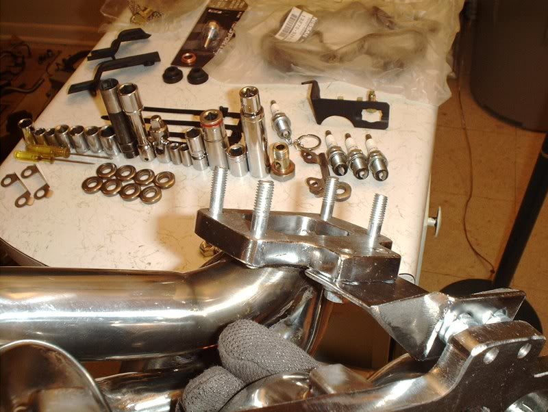
The manifold came with new studs and hardware, like a brace of some sort.
I went ahead and installed the brace...
and seated the studs into place.
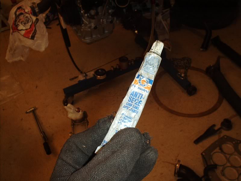
Don't forget to use some anti-seize on the studs all around for the future if need be.

Take the turbo inlet gasket...
and place it on.
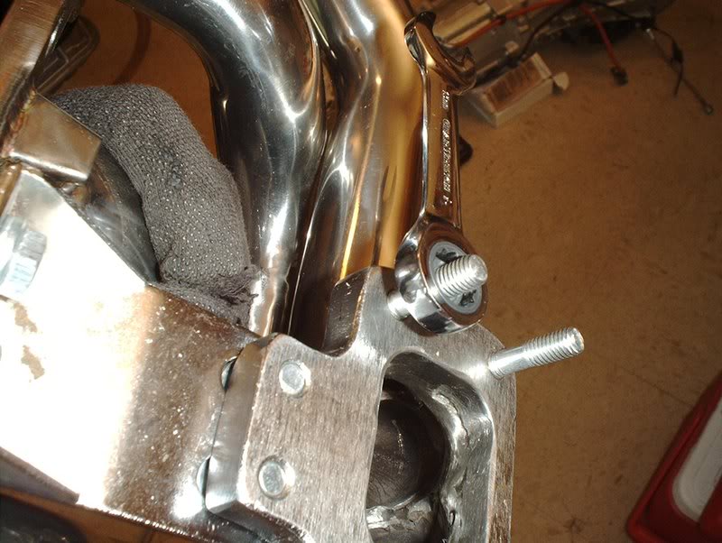
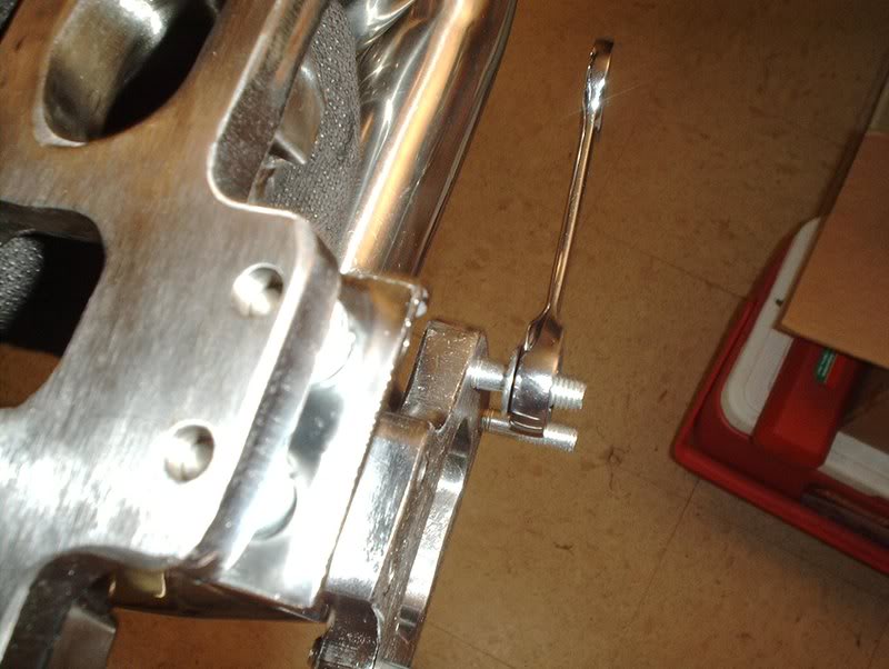
I had to back it off a bit so that I would have room to put the locking tabs and nuts on.
Like so.
The manifold came with some nuts but they have flared ends so they pretty much covered the tabs on the locking plates so I used a set of M8-1,25 from the parts store instead. These are just like the stock nuts that I originally removed from the turbo and they don't have flared ends so you can fold the tabs over these nuts...can I say that?!
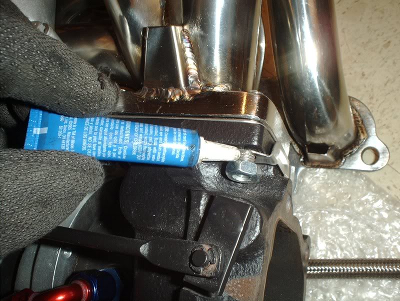
While I was at it I decided to use some threadlocker as well because I had been reading a lot of threads about how these have a tendency to back off because of all the pressure from the turbo.
Examples...
...
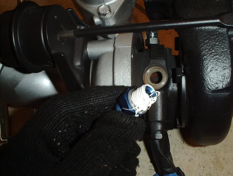
I put the nuts on next. Space is tight so some of them are pretty tricky to get on unless you've got those little monkey hands.
To get one of the nuts near the top of the turbo inlet on, I had to remove the water line for extra space.
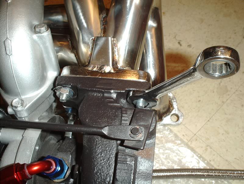
Next, I tightened and torqued to 16-22ft.lbs.
Use a set of needlenose pliers to fold the locking tabs over the nuts.
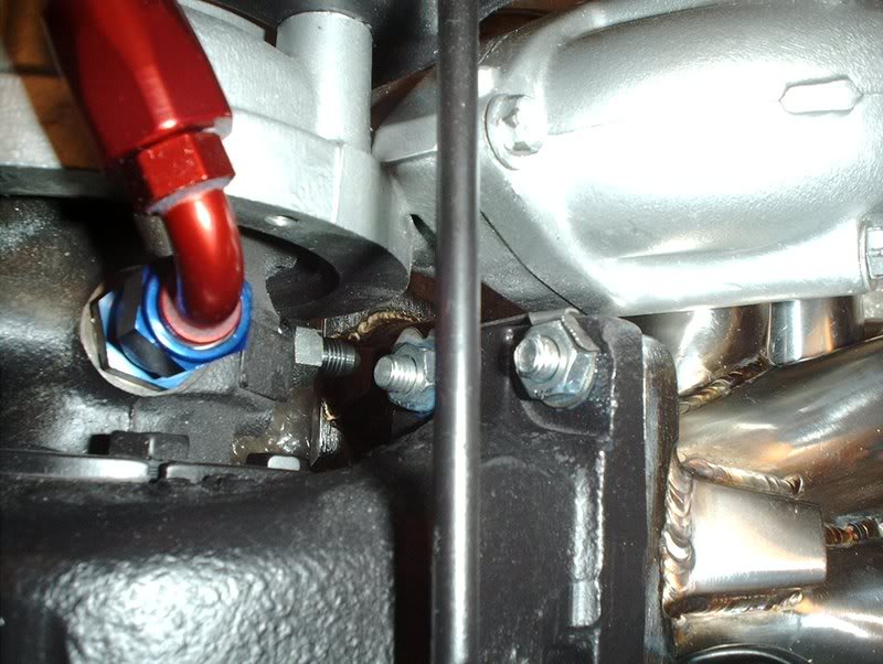
Like so.
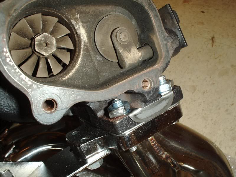
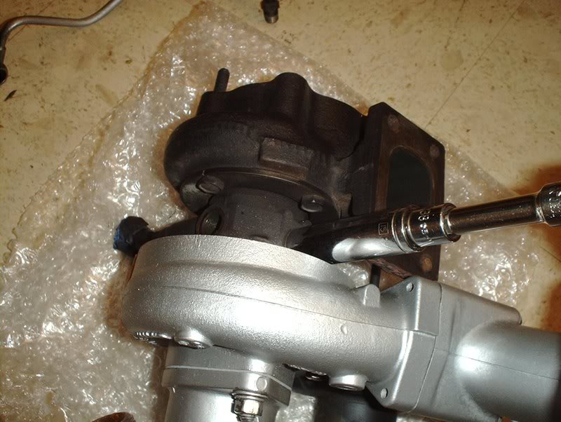
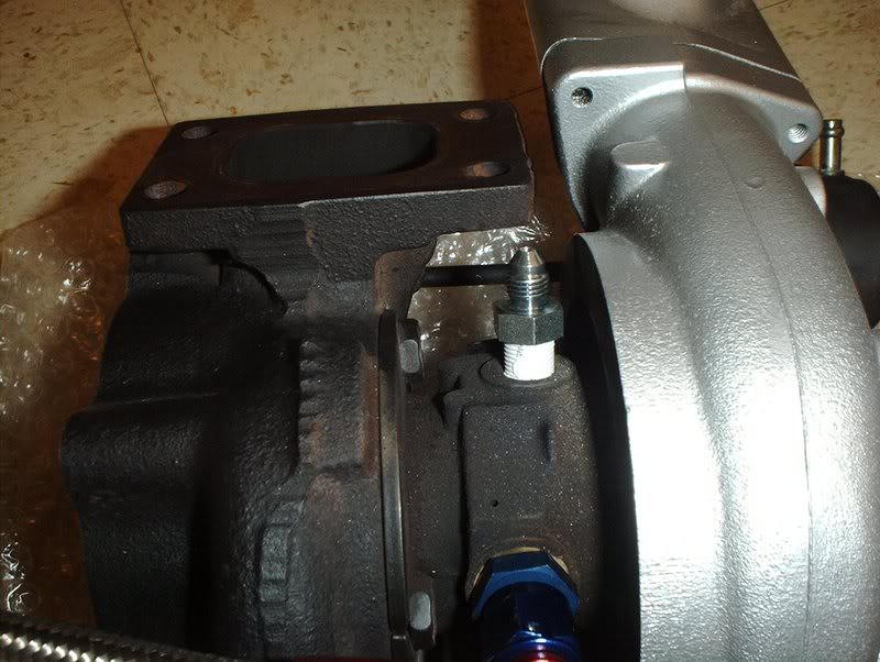
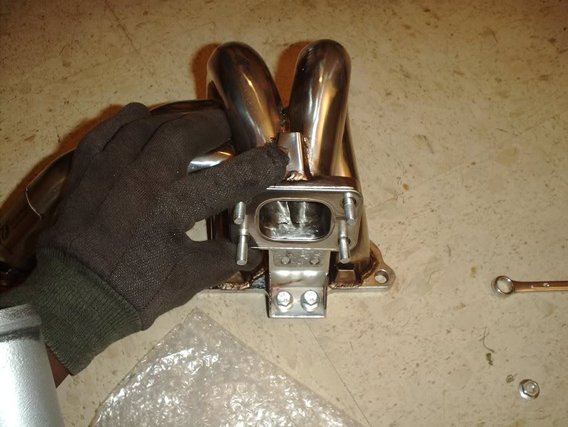
The nut on the inlet side was hard to get to with the pliers so I just used a screwdriver and a hammer to bend the tab on this one. This is where the hammer comes into play. The manifold is mounted to the turbo so now you can install it on the block.
Exhaust ports.
I had some old gasket still on the ports so I used a razorblade to remove it and clean the area before I placed my manifold gasket on.
Take the exhaust manifold gasket...
and place it on.
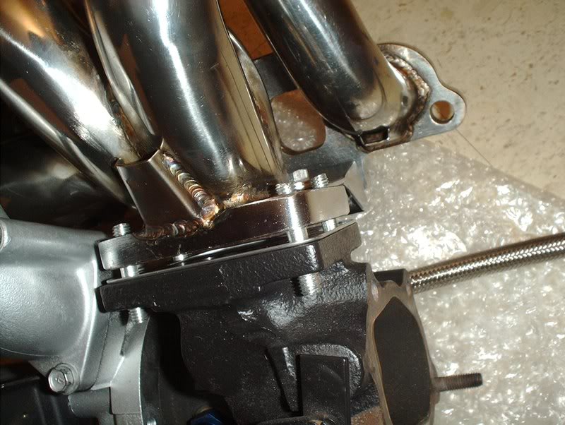
Take the turbo and mount it on the block.
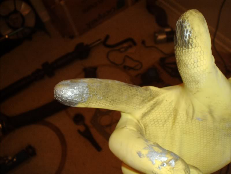
Break out your cleanin' gloves and lube up the studs with some anti-seize before you put the hardware on. This stuff STINKS!!!!
Place your exhaust washers and nuts on.
From here you need to break out the FSM(factory service manual) because the nuts need to be tightened in a specific order.
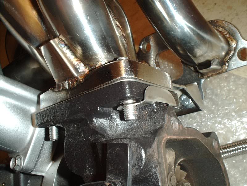
Tighten and torque to 27-35ft.lbs...
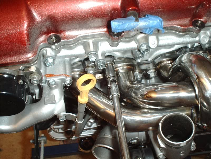
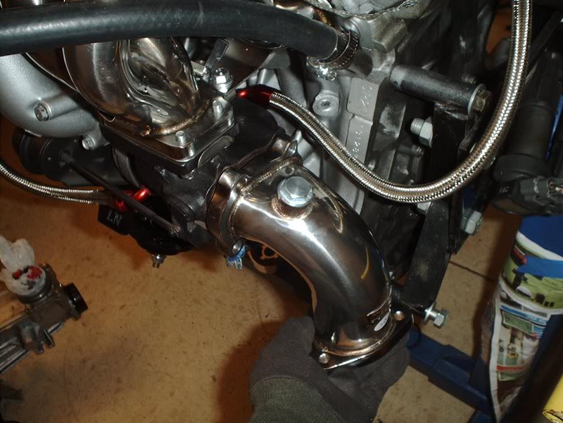
and the manifold/turbo is mounted.
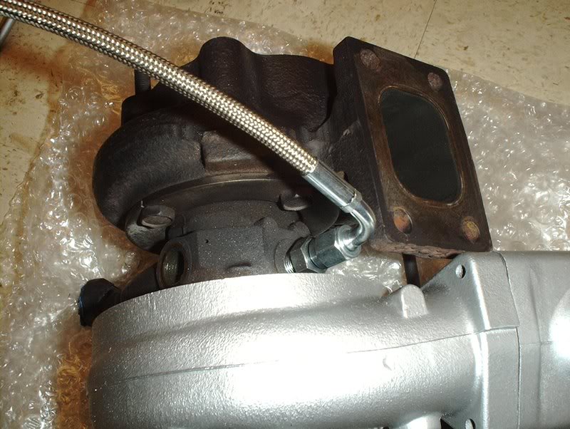
Now on to the turbo lines.
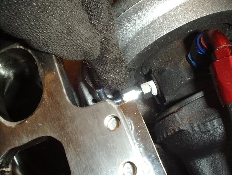
I started with the water line.
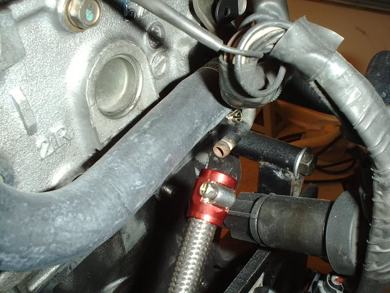
On a S13 SR it will connect here. On a S14/S15 SR, it connects to the water neck unless you get a S14/S15 water neck and use it on a S13 engine...you confused yet?
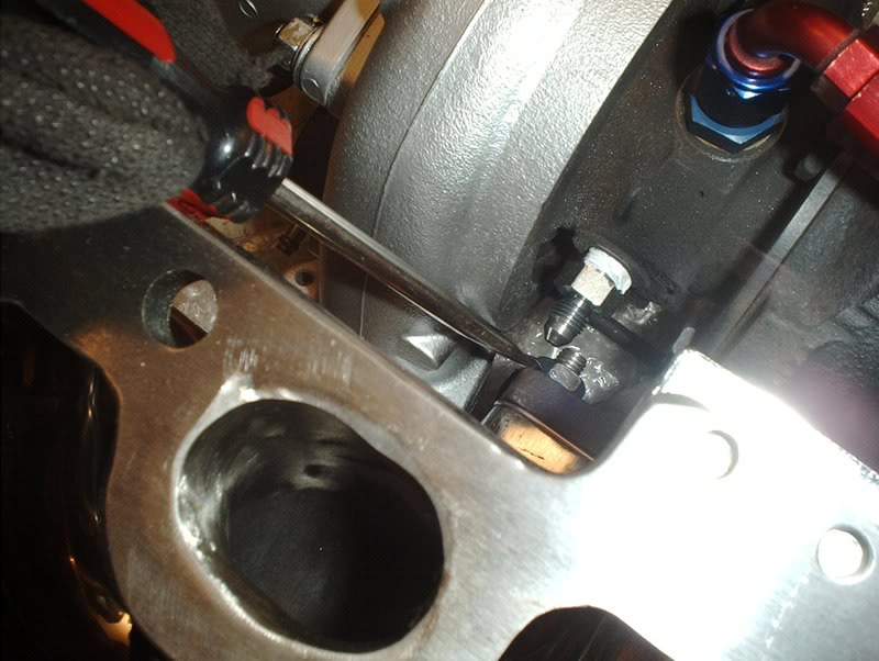
Use a screwdriver to loosen the fitting...
and place it on the hardline here. Tighten it back with the screwdriver.
Water line.
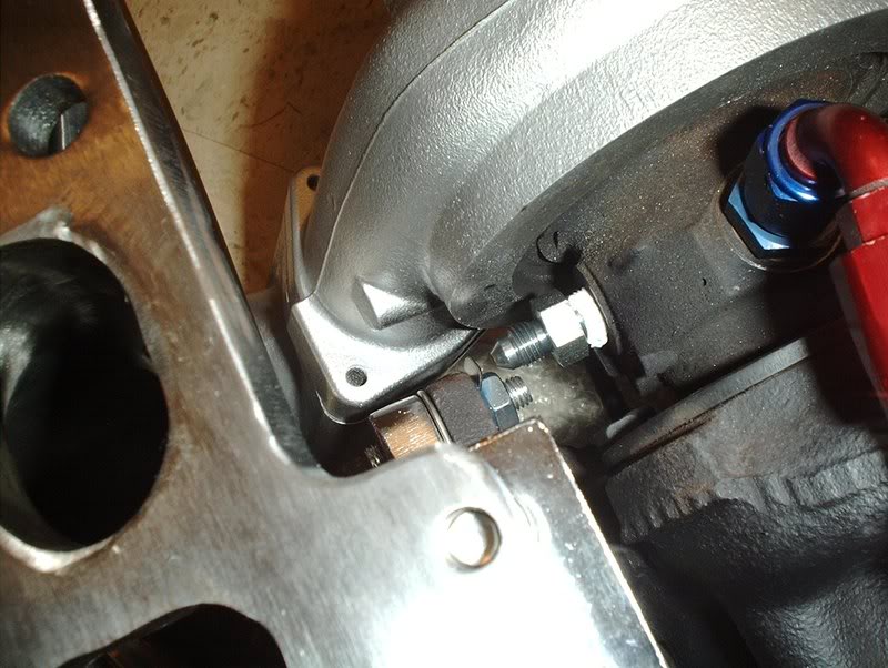
I moved to the next water line.
Take the banjo fitting off, the two crush washers that should be supplied and the stock banjo bolt. Like my new gloves, hobo style FTMFW!
Put two crushers on both sides of the banjo bolt and install.
Tighten and torque to 14-23ft.lbs.
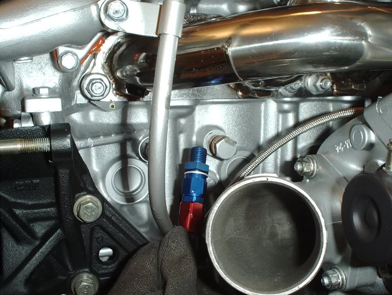
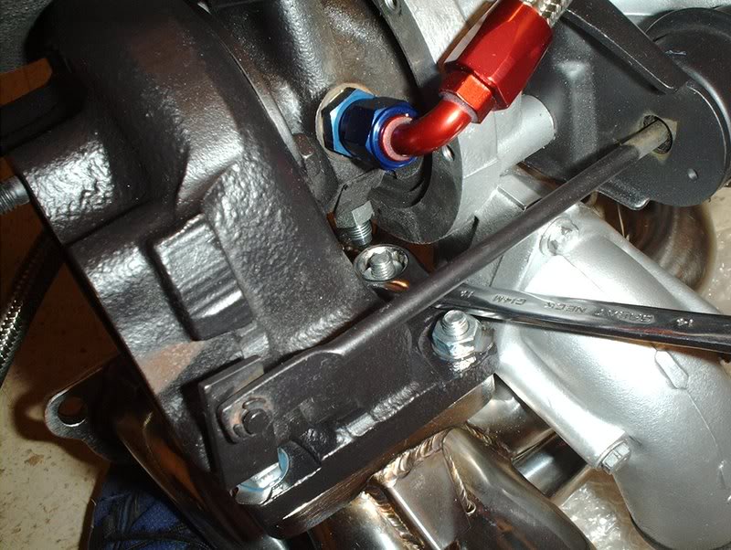
Lastly, the oil outlet line.
Remove the fitting and the crush washer.
Place it on the block...
tighten and torque to 14-23ft.lbs.
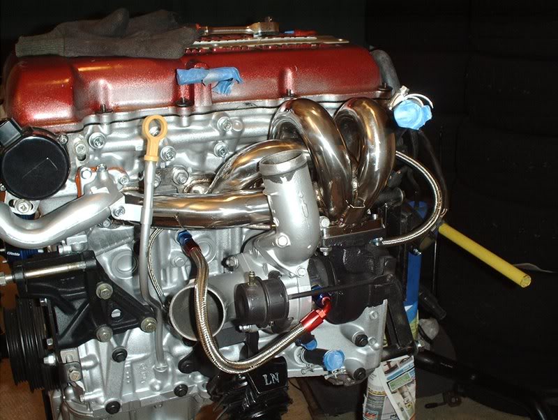
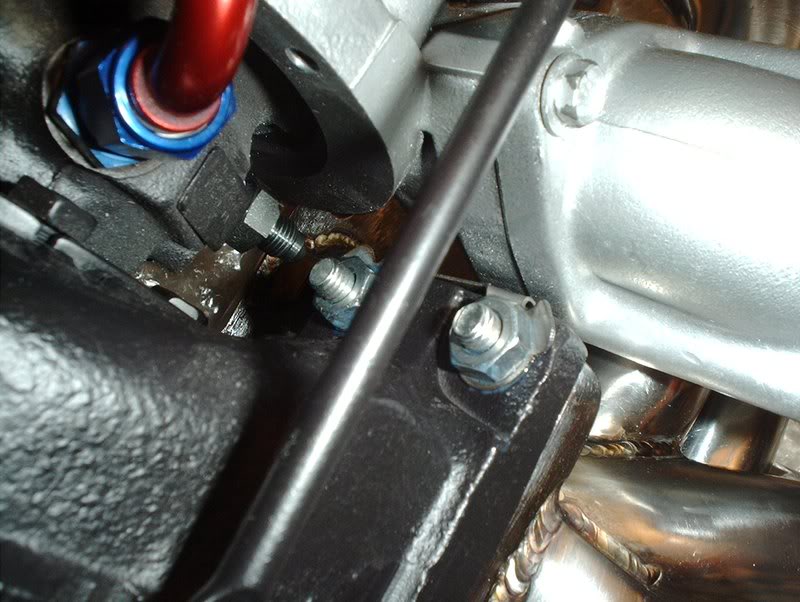
Almost complete!
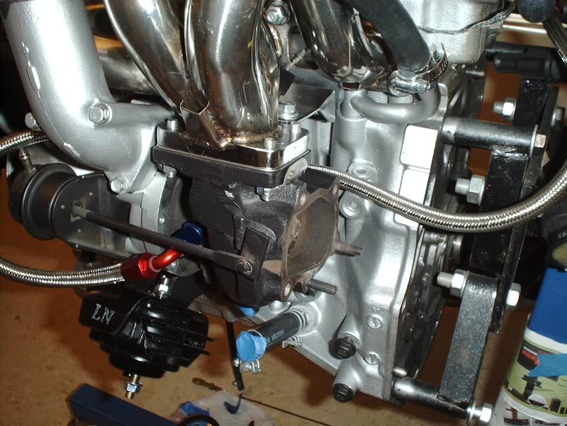
I can't install the turbo outlet yet because the people I ordered it from forgot to pack in the hardware(studs) so I'll have to wait on that.
I also don't have a O2 sensor or adapter yet.
TO BE CONTINUED...
Tools needed:
Socket wrench
Socket extension
13mm socket
14mm socket
15mm socket
Needlenose pliers
Screwdriver
Hammer(you'll see why later)
Anti-seize
Threadlocker
Razorblade
I got a setup in the other day.
Megan Racing turbo manifold.
Megan Racing turbo outlet.
OEM T25 S13 Turbo
OEM multilayer metal exhaust manifold gasket part#:14036-75F00.
OEM metal turbo inlet gasket part#:14415-17M00.
OEM metal turbo outlet gasket part#:14445-26E00.
OEM turbo locking plates part#:14495-40P10.
OEM exhaust manifold washer part#:14037-42L02.
OEM exhaust manifold nut part#:08912-8401A
The manifold came with new studs and hardware, like a brace of some sort.
I went ahead and installed the brace...
and seated the studs into place.
Don't forget to use some anti-seize on the studs all around for the future if need be.
Take the turbo inlet gasket...
and place it on.
I had to back it off a bit so that I would have room to put the locking tabs and nuts on.
Like so.
The manifold came with some nuts but they have flared ends so they pretty much covered the tabs on the locking plates so I used a set of M8-1,25 from the parts store instead. These are just like the stock nuts that I originally removed from the turbo and they don't have flared ends so you can fold the tabs over these nuts...can I say that?!
While I was at it I decided to use some threadlocker as well because I had been reading a lot of threads about how these have a tendency to back off because of all the pressure from the turbo.
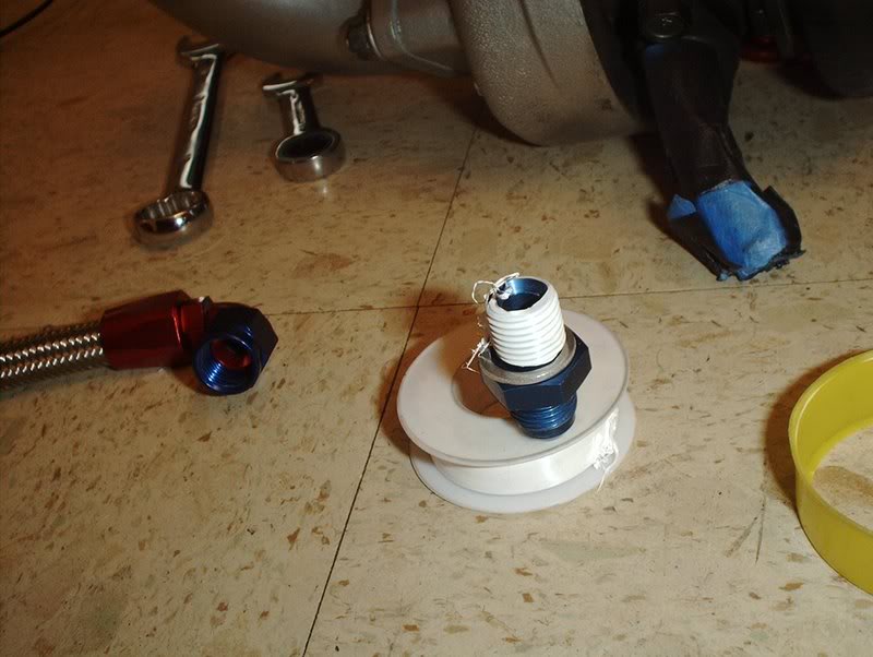
Examples...
...
I put the nuts on next. Space is tight so some of them are pretty tricky to get on unless you've got those little monkey hands.
To get one of the nuts near the top of the turbo inlet on, I had to remove the water line for extra space.
Next, I tightened and torqued to 16-22ft.lbs.
Use a set of needlenose pliers to fold the locking tabs over the nuts.
Like so.
The nut on the inlet side was hard to get to with the pliers so I just used a screwdriver and a hammer to bend the tab on this one. This is where the hammer comes into play. The manifold is mounted to the turbo so now you can install it on the block.
Exhaust ports.
I had some old gasket still on the ports so I used a razorblade to remove it and clean the area before I placed my manifold gasket on.
Take the exhaust manifold gasket...
and place it on.
Take the turbo and mount it on the block.
Break out your cleanin' gloves and lube up the studs with some anti-seize before you put the hardware on. This stuff STINKS!!!!
Place your exhaust washers and nuts on.
From here you need to break out the FSM(factory service manual) because the nuts need to be tightened in a specific order.
Tighten and torque to 27-35ft.lbs...
and the manifold/turbo is mounted.
Now on to the turbo lines.
I started with the water line.
On a S13 SR it will connect here. On a S14/S15 SR, it connects to the water neck unless you get a S14/S15 water neck and use it on a S13 engine...you confused yet?
Use a screwdriver to loosen the fitting...
and place it on the hardline here. Tighten it back with the screwdriver.
Water line.
I moved to the next water line.
Take the banjo fitting off, the two crush washers that should be supplied and the stock banjo bolt. Like my new gloves, hobo style FTMFW!
Put two crushers on both sides of the banjo bolt and install.
Tighten and torque to 14-23ft.lbs.
Lastly, the oil outlet line.
Remove the fitting and the crush washer.
Place it on the block...
tighten and torque to 14-23ft.lbs.
Almost complete!
I can't install the turbo outlet yet because the people I ordered it from forgot to pack in the hardware(studs) so I'll have to wait on that.
I also don't have a O2 sensor or adapter yet.
TO BE CONTINUED...
Last edited by positron; 06-13-2008 at 11:31 AM.