
My S13 SR20DET Prep
 04-26-2008, 04:58 PM
#151
Registered User
Join Date: Jan 2008
Location: wisconsin
Posts: 68
i dont think its the plug releasing power cause why would they make them liek that then right? cause technically wouldnt u get shocked if u touched it then? but yea iv thrown them at windows its not the charge its the throw lol
 04-26-2008, 05:32 PM
#152
Contributing Member
Thread Starter
Join Date: Sep 2002
Location: Starkville, MS.
Posts: 1,192
Altima Fan Modification w/Koyo Radiator
While I had my fans broken down into pieces I thought this would be the best time to experiment with the shroud and see how I could mount it best to the radiator. These modifications were made with the purpose of using the Altima fans on a Koyo Aluminum radiator. Keep in mind that this is a total ghetto-fab job. It works but don't look so good.
Tools needed:
10mm bolts
10mm nuts
Small metal bracket(about an inch in length)
Drill
Zipties
Knife/blade/razor
Sandpaper or a sanding block(medium grit)
I was able to nab a set of Altima fans for use in my swap but the problem is that they don't exactly mount up properly to the Koyo/SR swap unless you modify. Untouched, the fans only line up with the top left mounting point on the Koyo and even then they aren't flat against the rad because of being blocked by the lower portion of the fan shroud sitting on the lower rad outlet and the A/C condenser brackets. I already explained earlier what I had to modify on the lower portion of the fan shroud in order to get the fans to sit flush against the radiator so now I'll go into detail on what I did to get them properly mounted to the Koyo. I was originally just going to use the Permacool fan mounting kit that I had with the zipties but I was informed that because of the wieght of these fans, that would destroy the radiator fins. It's just too heavy to be mounted in that fashion, much heavier than the Permacool.
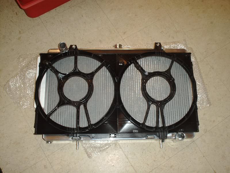
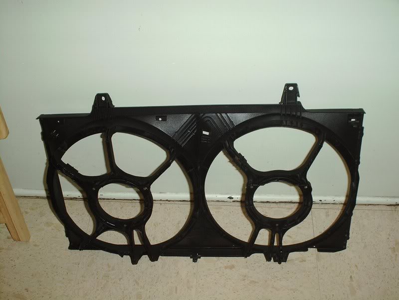
As you can see here the Altima fans cover the entire surface area of the radiator.
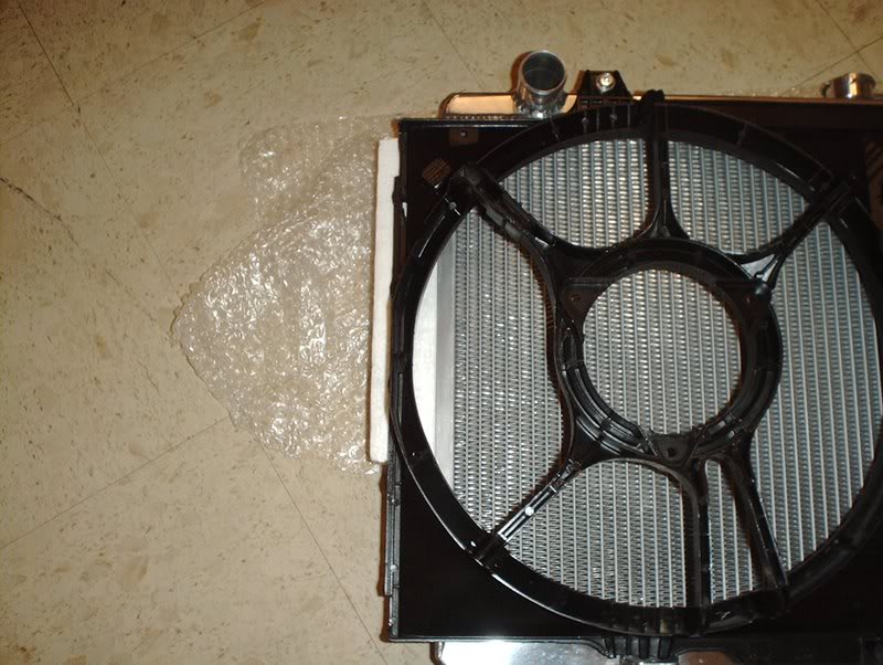
They even over lap a bit on the left....
and on the right side but that's not a problem.
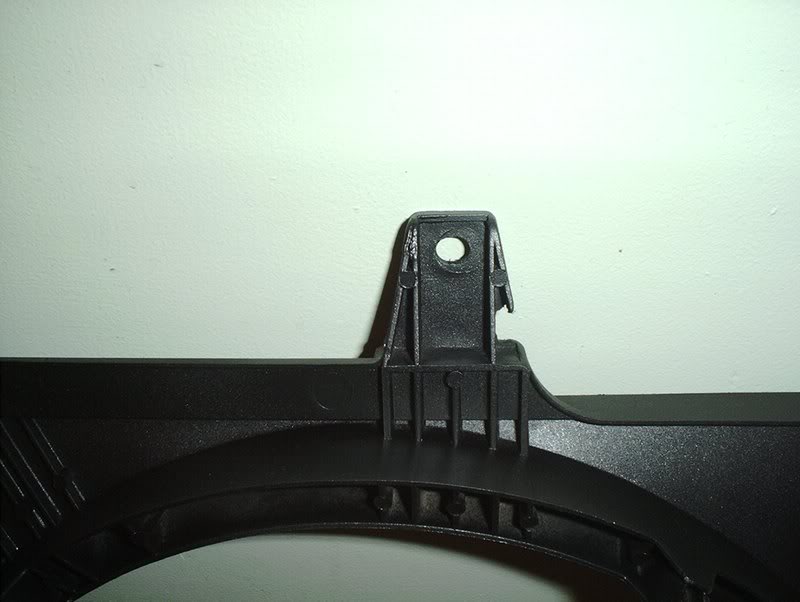
Here are the four points of mounting that I used. This is the upper left side, this is the only mounting point that lined up to the rad mounts.
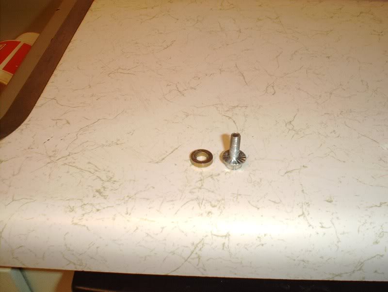
Just use one 10mm bolt and a small spacer if your bolt is too long to take out the slack.
For the upper left side the mounting point is about a half inch away from the mounting point so what I did was...
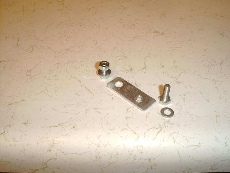
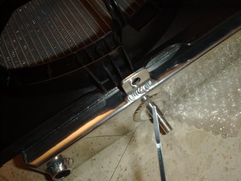
Take a one inch piece of metal and line it up to the rad mount and the fan mount...
mark two spots on it for where the holes need to be drilled like so...
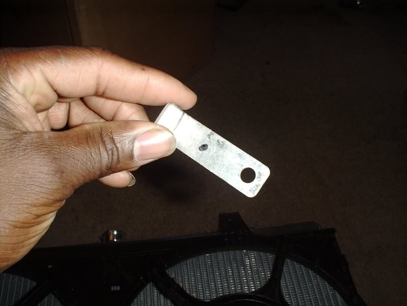
and use a drill to make the holes in the metal. I went back and cut off the excess metal...well, I didn't actually cut it because I didn't have a tool so I just bent it back and forth with a set of pliers until it snapped off and then I sanded the edges smooth.
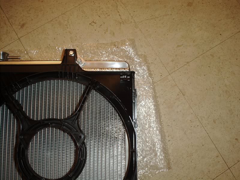
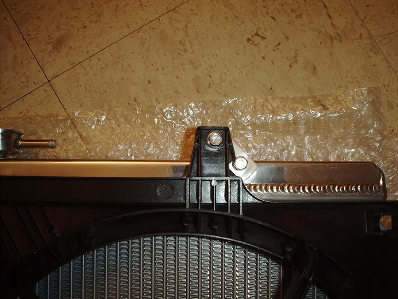
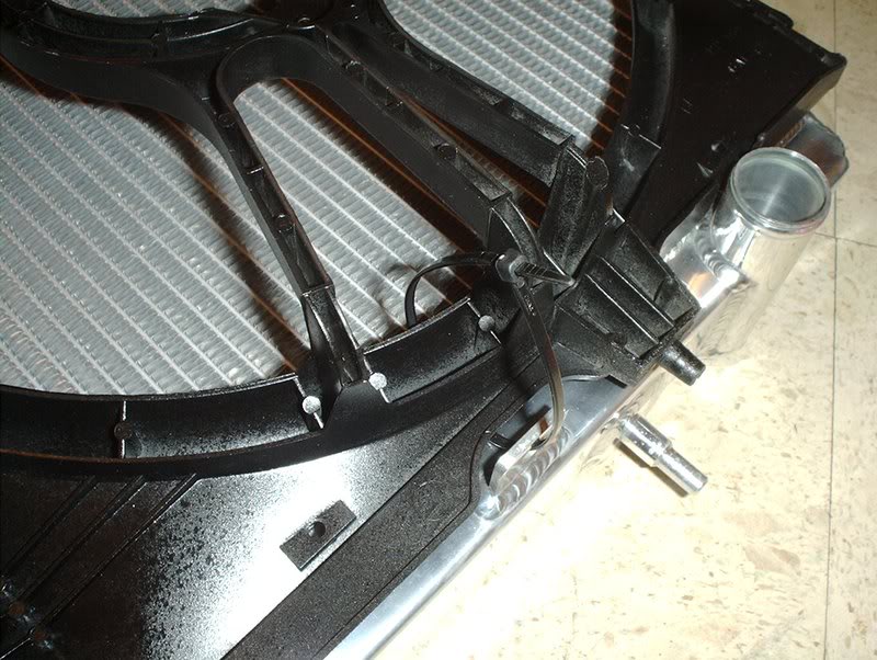
I was able to put the bracket on the rad and the fan mounts diagonally. I used a 10mm bolt and nut on the fan shroud and I used a 10mm bolt on the rad mount with a spacer for the slack.
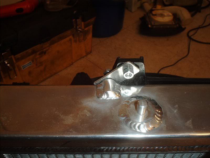
Front shot.
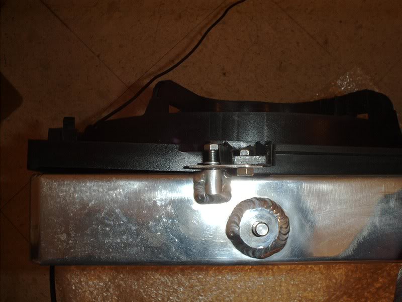
Top shot. Like I said GHETTO FABULOUSNESS!!!! Bolts not threaded in all the way but that's because I'm not ready to mount it. I still have to put the fans and motors back in....but it works!
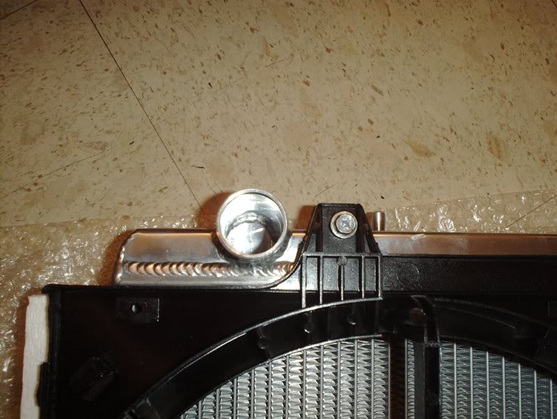
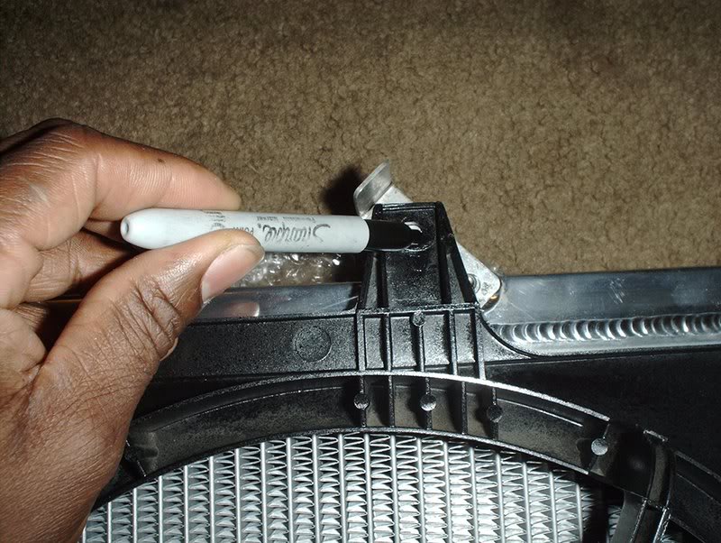
While I was doing this I ran into a small problem. The bolt didn't line up straight with the rad mount because the side of the mount on the fan shroud was in contact with the bolt head pushing it to the side.
This was easily fixed by just cutting a small wafer thin piece of plastic off the shroud here and sanding it down smooth thus giving the bolt head plenty of space to be threaded in to the rad. I still need to work on that because it just looks bad!
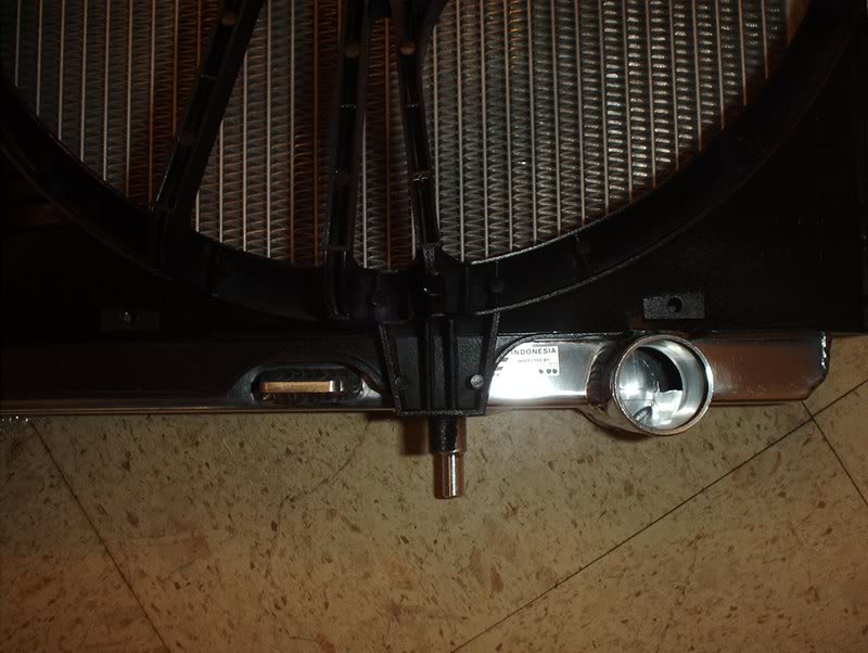
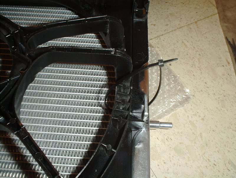
On the lower left side as I explained earlier in the thread, I just cut a small section off here and sanded it down to sit flush. This needs to be worked on too...even'er out!
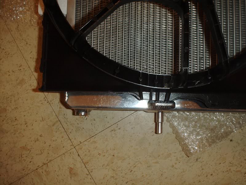
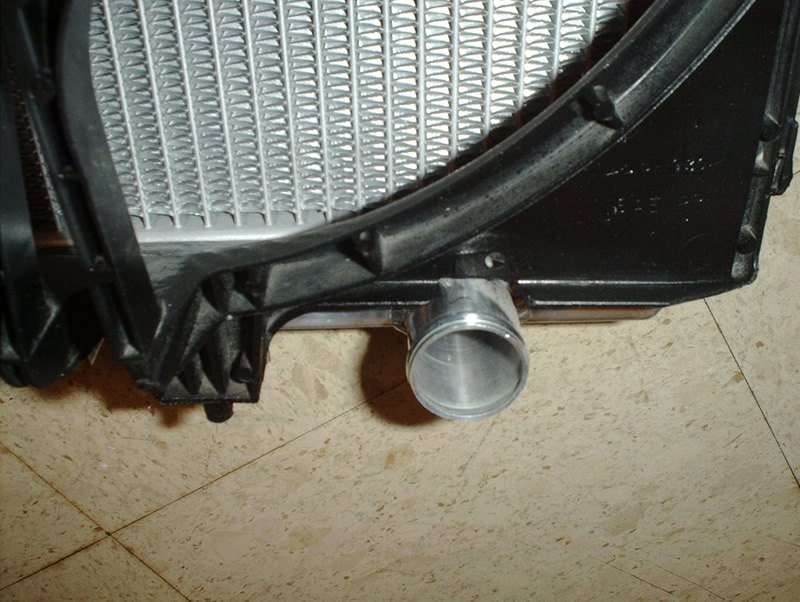
And on the lower right side I cut a thin section off so the shroud could fit above the lower radiator outlet.
FOR MOUNTING THE BOTTOM OF THE FAN SHROUD I DID THE FOLLOWING.
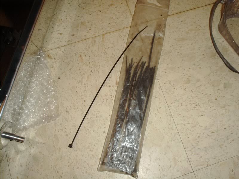
Trusty zipties. I figured that since the top of the fan is bolted in nice and tight then I could get away with zips on the bottom.
I'm going to run two to three zipties per side throught the holes in the A/C condensor mounts on the bottom of the Koyo...
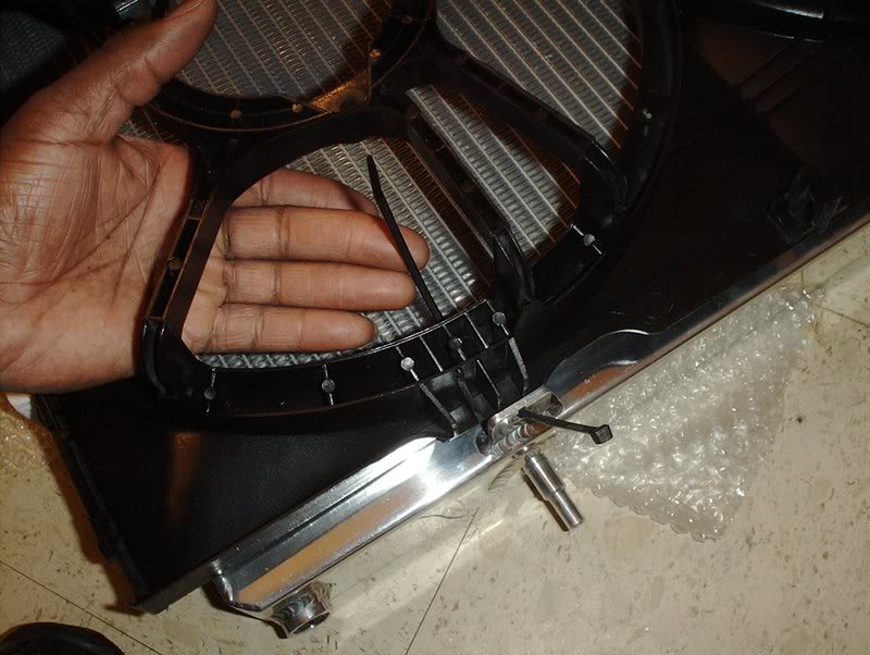
and around the fan shroud like so.
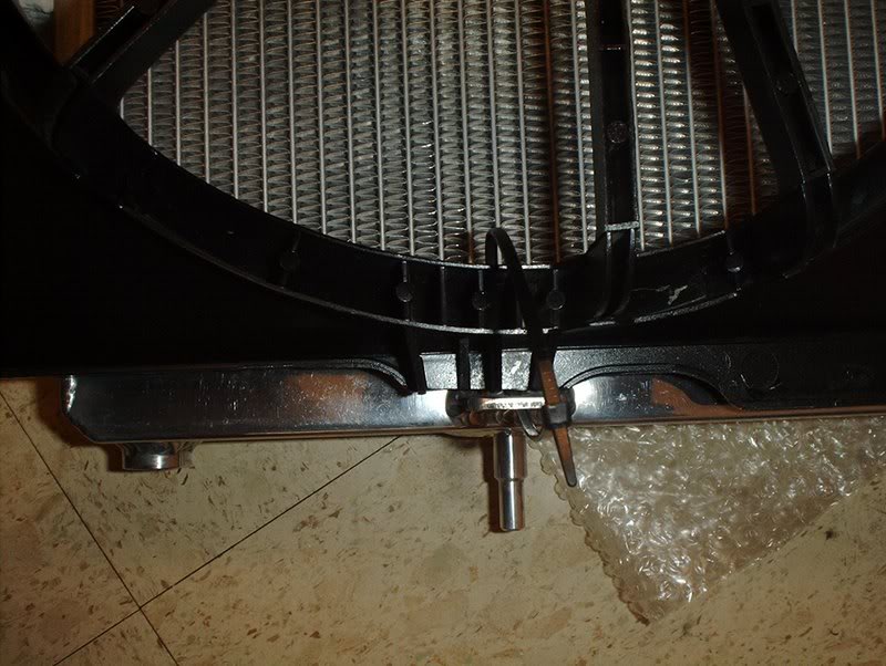
Tie them off and cut the excess.
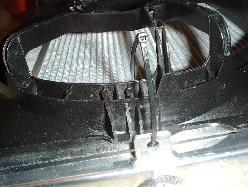
I think that this could work unless the heat takes out the zipties so if anyone has another idea here let me know.
Before I put the fans and motors back into the shroud I decided to work on those cut spots, clean it some more and lay a coat of Krylon fusion on to give it a refresh look.
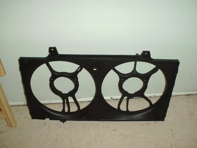
This stuff bond pretty good to plastic but the extreme heat will soon take care of that yes....I gave it a shot! Now for the wiring and a fan controller.
TO BE CONTINUED
Tools needed:
10mm bolts
10mm nuts
Small metal bracket(about an inch in length)
Drill
Zipties
Knife/blade/razor
Sandpaper or a sanding block(medium grit)
I was able to nab a set of Altima fans for use in my swap but the problem is that they don't exactly mount up properly to the Koyo/SR swap unless you modify. Untouched, the fans only line up with the top left mounting point on the Koyo and even then they aren't flat against the rad because of being blocked by the lower portion of the fan shroud sitting on the lower rad outlet and the A/C condenser brackets. I already explained earlier what I had to modify on the lower portion of the fan shroud in order to get the fans to sit flush against the radiator so now I'll go into detail on what I did to get them properly mounted to the Koyo. I was originally just going to use the Permacool fan mounting kit that I had with the zipties but I was informed that because of the wieght of these fans, that would destroy the radiator fins. It's just too heavy to be mounted in that fashion, much heavier than the Permacool.
As you can see here the Altima fans cover the entire surface area of the radiator.
They even over lap a bit on the left....
and on the right side but that's not a problem.
Here are the four points of mounting that I used. This is the upper left side, this is the only mounting point that lined up to the rad mounts.
Just use one 10mm bolt and a small spacer if your bolt is too long to take out the slack.
For the upper left side the mounting point is about a half inch away from the mounting point so what I did was...
Take a one inch piece of metal and line it up to the rad mount and the fan mount...
mark two spots on it for where the holes need to be drilled like so...
and use a drill to make the holes in the metal. I went back and cut off the excess metal...well, I didn't actually cut it because I didn't have a tool so I just bent it back and forth with a set of pliers until it snapped off and then I sanded the edges smooth.
I was able to put the bracket on the rad and the fan mounts diagonally. I used a 10mm bolt and nut on the fan shroud and I used a 10mm bolt on the rad mount with a spacer for the slack.
Front shot.
Top shot. Like I said GHETTO FABULOUSNESS!!!! Bolts not threaded in all the way but that's because I'm not ready to mount it. I still have to put the fans and motors back in....but it works!
While I was doing this I ran into a small problem. The bolt didn't line up straight with the rad mount because the side of the mount on the fan shroud was in contact with the bolt head pushing it to the side.
This was easily fixed by just cutting a small wafer thin piece of plastic off the shroud here and sanding it down smooth thus giving the bolt head plenty of space to be threaded in to the rad. I still need to work on that because it just looks bad!
On the lower left side as I explained earlier in the thread, I just cut a small section off here and sanded it down to sit flush. This needs to be worked on too...even'er out!
And on the lower right side I cut a thin section off so the shroud could fit above the lower radiator outlet.
FOR MOUNTING THE BOTTOM OF THE FAN SHROUD I DID THE FOLLOWING.
Trusty zipties. I figured that since the top of the fan is bolted in nice and tight then I could get away with zips on the bottom.
I'm going to run two to three zipties per side throught the holes in the A/C condensor mounts on the bottom of the Koyo...
and around the fan shroud like so.
Tie them off and cut the excess.
I think that this could work unless the heat takes out the zipties so if anyone has another idea here let me know.
Before I put the fans and motors back into the shroud I decided to work on those cut spots, clean it some more and lay a coat of Krylon fusion on to give it a refresh look.
This stuff bond pretty good to plastic but the extreme heat will soon take care of that yes....I gave it a shot! Now for the wiring and a fan controller.
TO BE CONTINUED
04-26-2008, 07:58 PM
#153
no actually your wrong the spark plug ceramic is electrically charged and no your wouldnt get shocked havnt you ever touched both battery terminals of a car battery at the same time? you can hit the ceramic with a hammer to break it then grab a small piece of it and toss it at a glass and it will shatter try that with a normal small pebble you couldnt throw it hard enough to break glass
04-29-2008, 04:49 PM
#154
Contributing Member
Thread Starter
Join Date: Sep 2002
Location: Starkville, MS.
Posts: 1,192
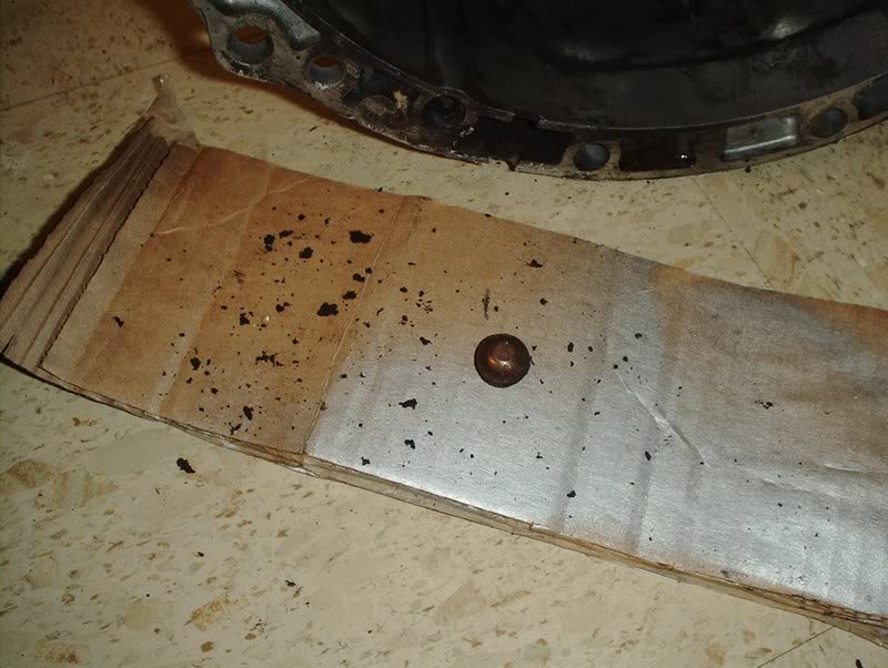
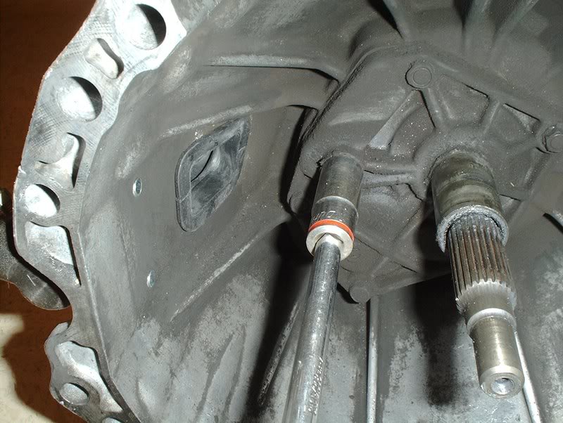
Clutch Pivot Ball...Problem?
I took the throwout bearing off my clutch today and when I removed the fork this came apart. I know nothing of the pivot ball so should I be worried here and what are my best options for a replacement? Will a KA24DE pivot ball work or should I just get one from SPL, Nismo, etc?
04-29-2008, 10:04 PM
#155
Contributing Member
Thread Starter
Join Date: Sep 2002
Location: Starkville, MS.
Posts: 1,192
Transmission-Dust Collar
I got some parts in today for my transmission.
Tools needed:
Rubber mallet
Block of wood/small hammer
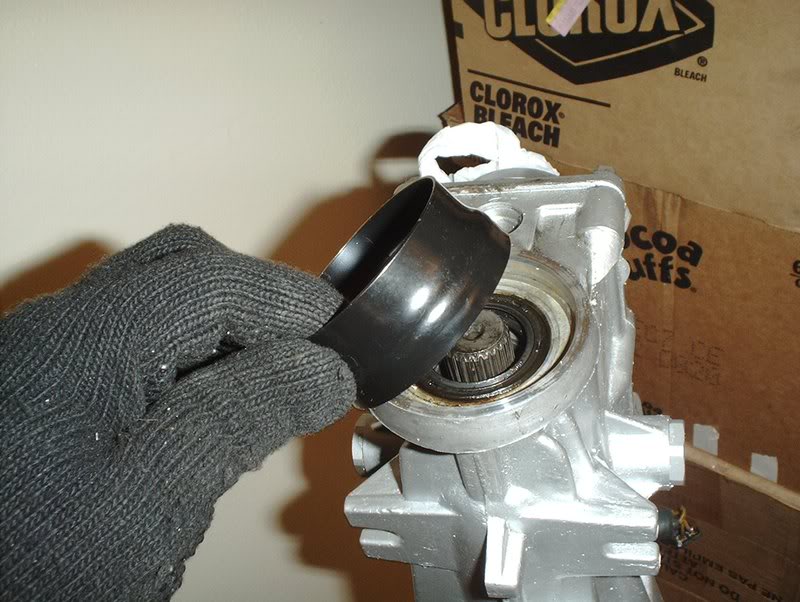
I read that you have to remove the SR dust collar and transfer a KA dust collar to the SR tranny in order to fit the OEM or aftermarket driveshafts on the SR transmission. I banged up my KA's dust collar trying to pry it off so I got a new one to replace it.
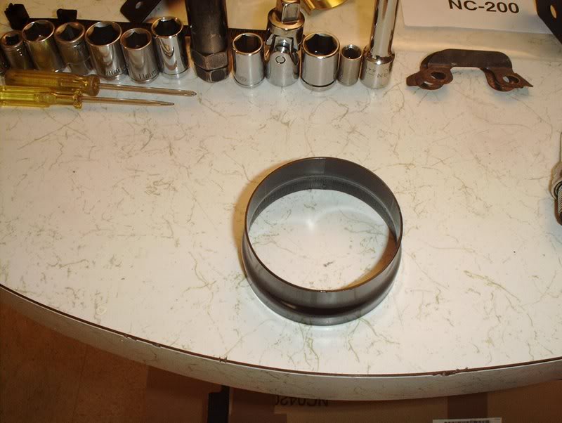
Transmission dust collar part#:32135-97L00.
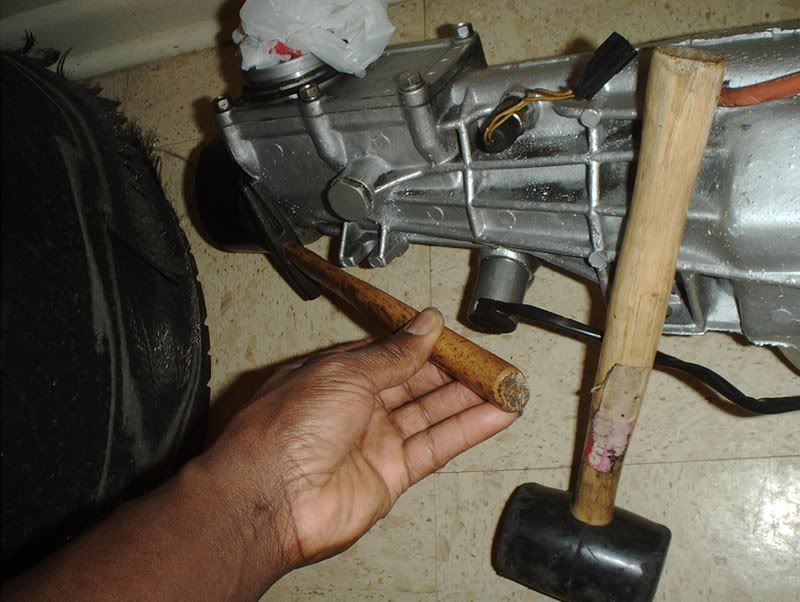
They say use a block of wood but I didn't have one so I just used this small hammer and a rubber mallet. Place whatever you plan to use against the dust collar, whack it...
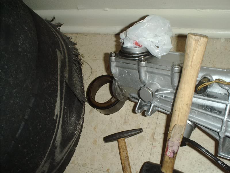
and it comes off like so.
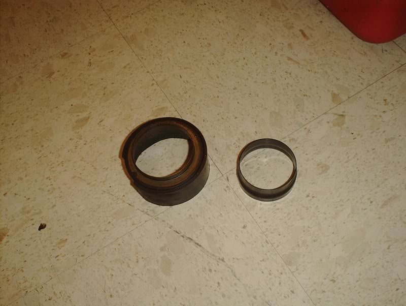
The SR dust collar on the left is quite noticeably bigger than the KA dust collar on the right.
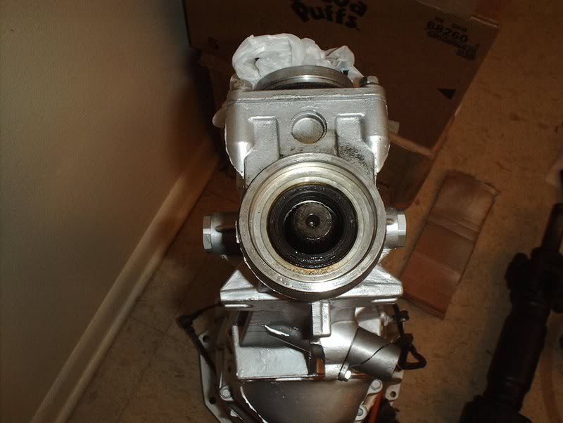
Wipe the area down.
Put your KA dust collar in and tap it in place.
And you are done.
Tools needed:
Rubber mallet
Block of wood/small hammer
I read that you have to remove the SR dust collar and transfer a KA dust collar to the SR tranny in order to fit the OEM or aftermarket driveshafts on the SR transmission. I banged up my KA's dust collar trying to pry it off so I got a new one to replace it.
Transmission dust collar part#:32135-97L00.
They say use a block of wood but I didn't have one so I just used this small hammer and a rubber mallet. Place whatever you plan to use against the dust collar, whack it...
and it comes off like so.
The SR dust collar on the left is quite noticeably bigger than the KA dust collar on the right.
Wipe the area down.
Put your KA dust collar in and tap it in place.
And you are done.
04-29-2008, 11:35 PM
#156
Contributing Member
Thread Starter
Join Date: Sep 2002
Location: Starkville, MS.
Posts: 1,192
Transmission-Clutch Slave Cylinder
I swapped out the clutch slave cylinder today. I also swapped out my torn slave cylinder dust collar.
Tools needed:
Socket wrench
12mm socket
14mm wrench
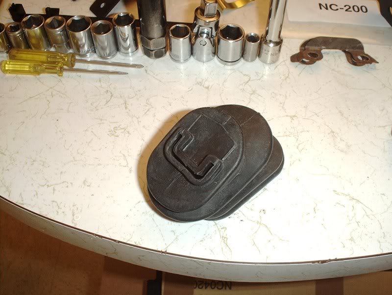
Slave cylinder dust collar Part#:30542-01S00.
Torn slave cylinder dust collar.
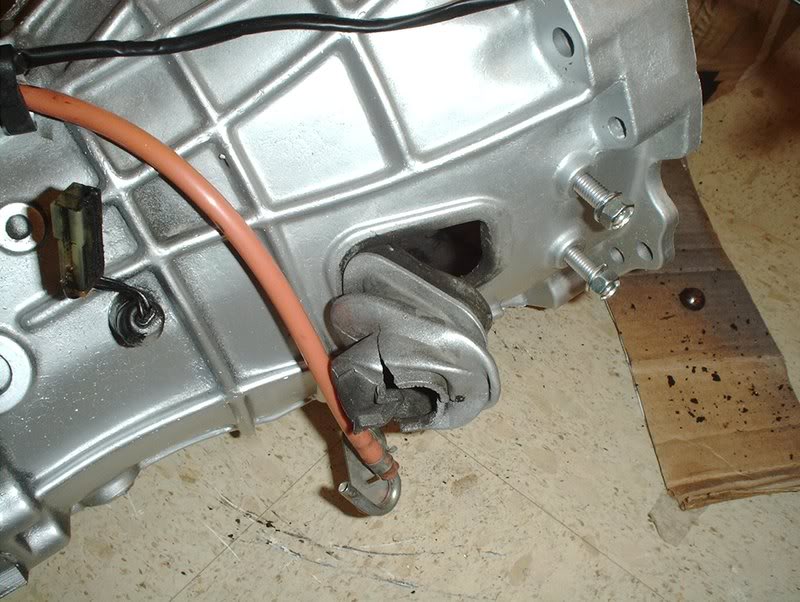
To remove it just grab a corner and pull.
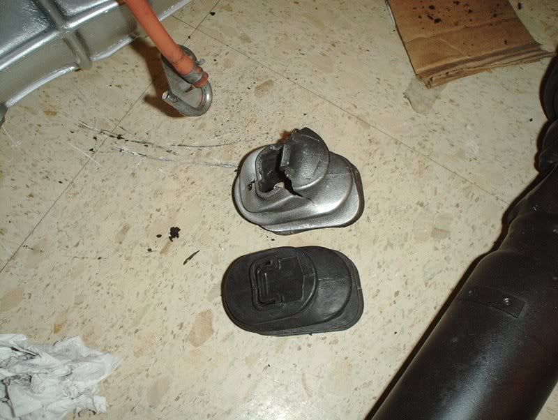
New vs. old.
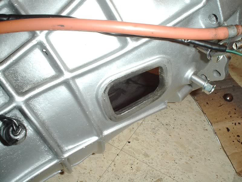
Take an opportunity to clean the area...
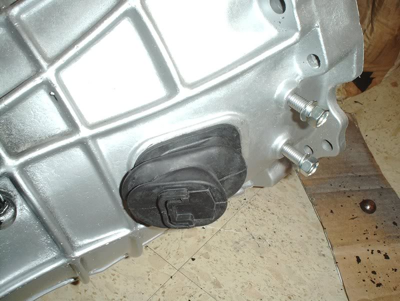
and put your new dust collar into place.
Now on to the slave cylinder
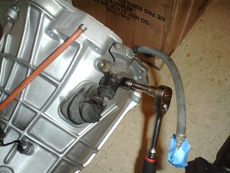
Use a 12mm socket to remove the two bolts holding the slave cylinder in.
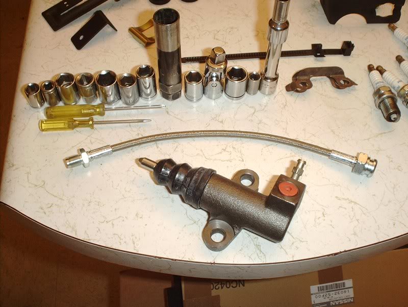
OEM slave cylinder and Project Nissan stainless steel clutch line.
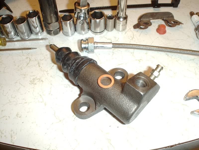
Crush washer for the clutch line. Part#:46237-S13001
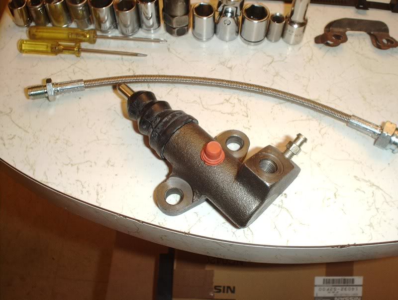
Remove the rubber stopper from the slave unit.
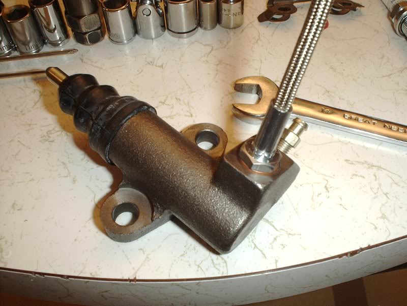
Use a 14mm wrench to put the clutch line in the cylinder.
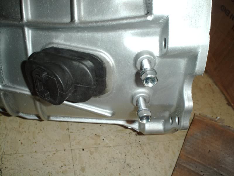
Got these bolts from Courtesy Nissan, Part#:08121-S13003, but you can also use bolts from the parts store M10-1,50X20MM, the same bolts you can use for the motor mount brackets.
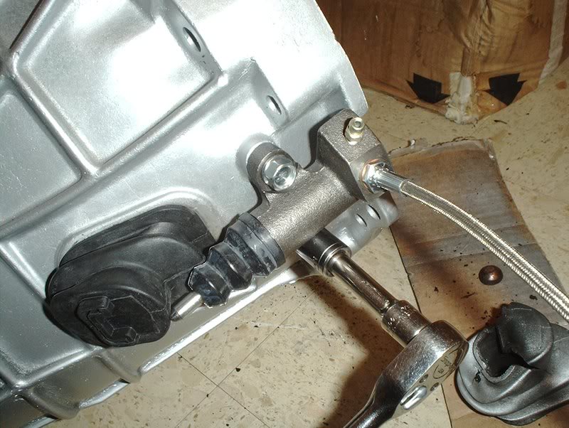
Use your socket wrench to put the new cylinder back onto the transmission and torque to 22-30ft.lbs.
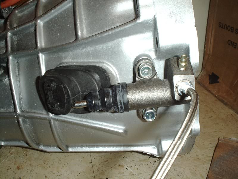
Finished.
TO BE CONTINUED...
P.S.
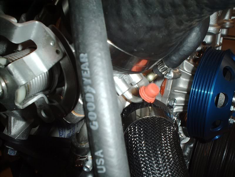
That rubber stopper on your new clutch slave cylinder is the perfect size to use for blocking that small port on the bottom of the throttlebody that you won't be using.
Tools needed:
Socket wrench
12mm socket
14mm wrench
Slave cylinder dust collar Part#:30542-01S00.
Torn slave cylinder dust collar.
To remove it just grab a corner and pull.
New vs. old.
Take an opportunity to clean the area...
and put your new dust collar into place.
Now on to the slave cylinder
Use a 12mm socket to remove the two bolts holding the slave cylinder in.
OEM slave cylinder and Project Nissan stainless steel clutch line.
Crush washer for the clutch line. Part#:46237-S13001
Remove the rubber stopper from the slave unit.
Use a 14mm wrench to put the clutch line in the cylinder.
Got these bolts from Courtesy Nissan, Part#:08121-S13003, but you can also use bolts from the parts store M10-1,50X20MM, the same bolts you can use for the motor mount brackets.
Use your socket wrench to put the new cylinder back onto the transmission and torque to 22-30ft.lbs.
Finished.
TO BE CONTINUED...
P.S.
That rubber stopper on your new clutch slave cylinder is the perfect size to use for blocking that small port on the bottom of the throttlebody that you won't be using.
Last edited by positron; 05-01-2008 at 10:33 AM.
04-29-2008, 11:58 PM
#157
Contributing Member
Thread Starter
Join Date: Sep 2002
Location: Starkville, MS.
Posts: 1,192
Harness Clips
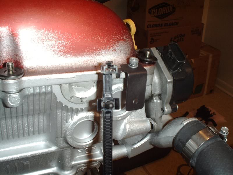
While I was ordering some stuff from Courtesy I took a browse through the clip section for the wiring and there are dozens of different clips for this car. I took a chance and ordered one that looked close to what I needed and it turned out to be the exact one. I cut these harness clips when I removed my wiring harness from the engine when I first got it and was just going to use zipties in their place but I found these instead.
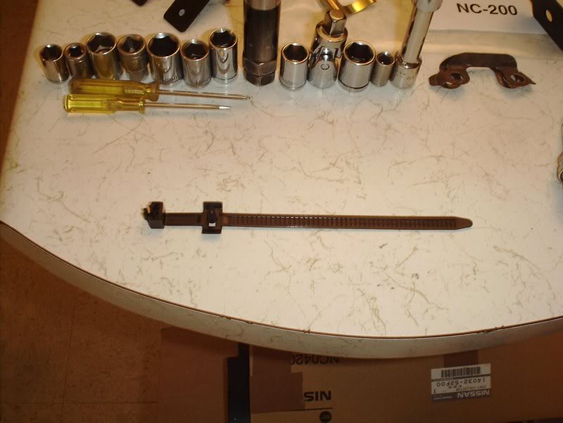
Wiring harness clip Part#:24222-S13007
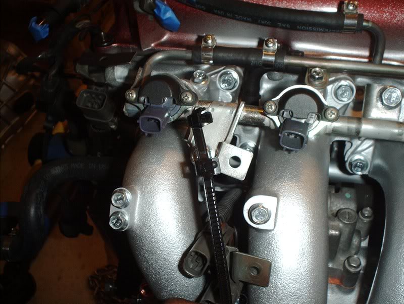
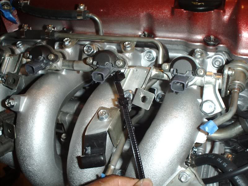
You can use them here on the fuel rail for the injector harnesses.
These zipties have a clip on them so you can clip them in the holes on the brackets.
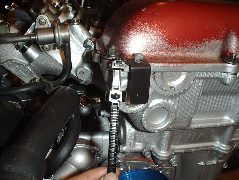
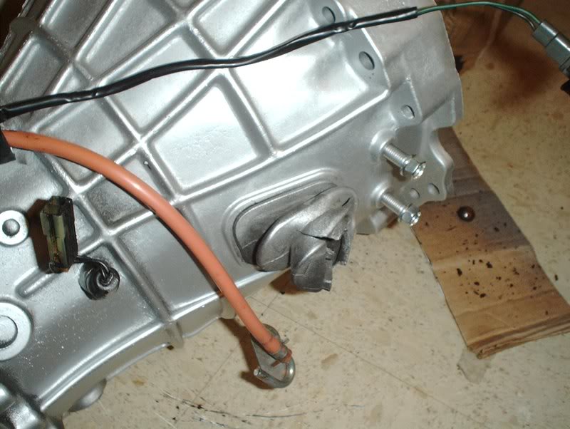
And here on the those two clips on the front of the engine for the MAF/PS/CAS part of the wiring harness that runs across the front.
Wiring harness clip Part#:24222-S13007
You can use them here on the fuel rail for the injector harnesses.
These zipties have a clip on them so you can clip them in the holes on the brackets.
And here on the those two clips on the front of the engine for the MAF/PS/CAS part of the wiring harness that runs across the front.
04-30-2008, 06:13 PM
#159
or u could just go oem its like $3 from courtasy parts lol all nissans use the same clutch pivot i have an extra 2 id send u one but there are in my tool box and i cant got to work cause my back is messed up from the accident
 05-01-2008, 01:42 AM
#161
Contributing Member
Thread Starter
Join Date: Sep 2002
Location: Starkville, MS.
Posts: 1,192
05-01-2008, 11:02 AM
#162
Contributing Member
Thread Starter
Join Date: Sep 2002
Location: Starkville, MS.
Posts: 1,192
Transmission-Gasket Replacement
I decided to see how difficult it would be to replace the gaskets on my transmission while I had the chance so I removed some parts to check the condition of the gaskets.
Tools needed:
Socket wrench
Socket extension
12mm socket
17mm socket
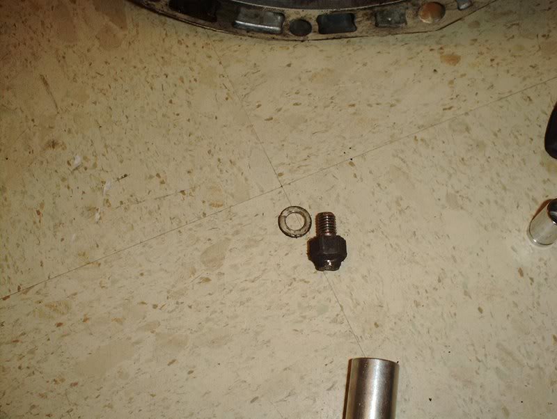
I had a broken clutch pivot ball so I started by removing that.
All you need is a 17mm deepwell socket to remove it.
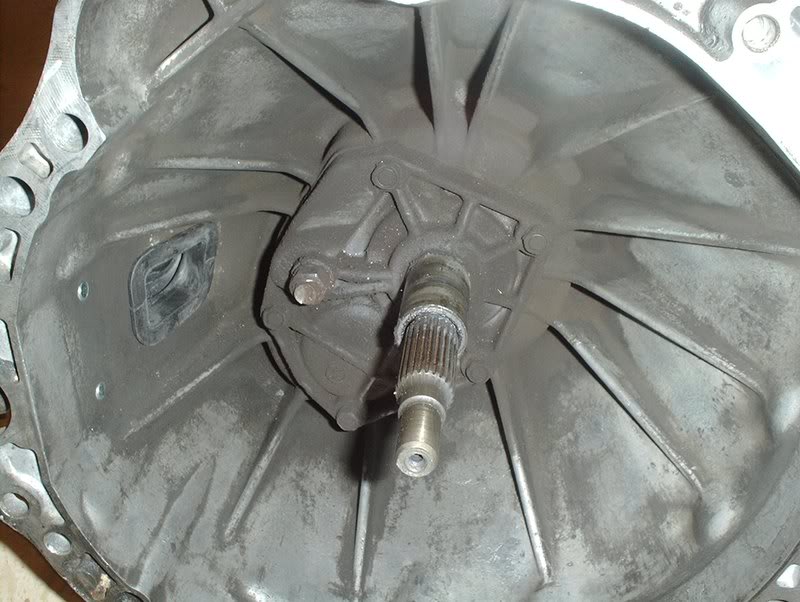
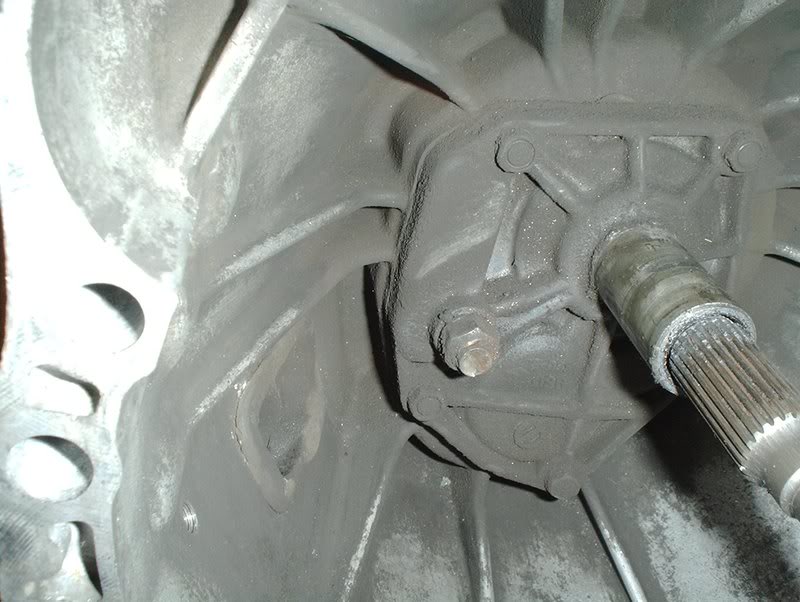
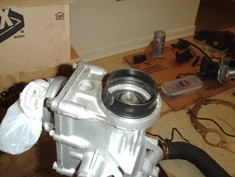
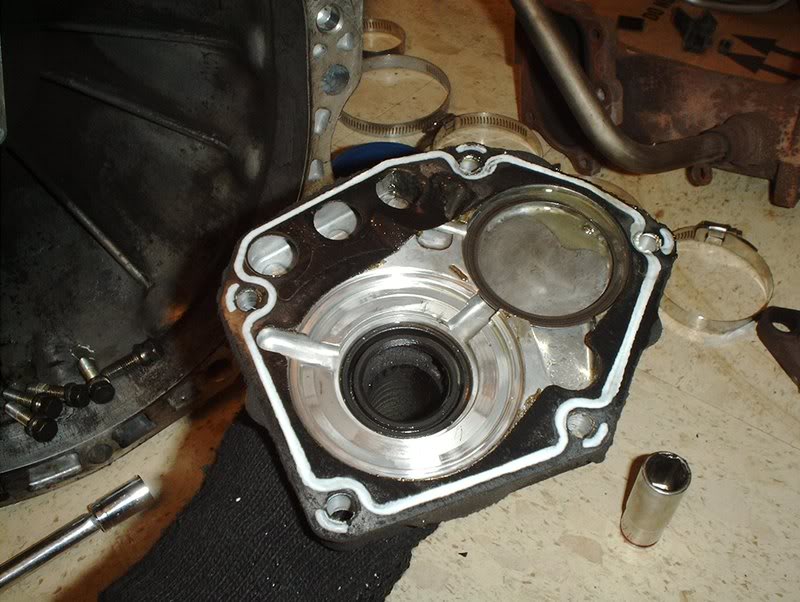
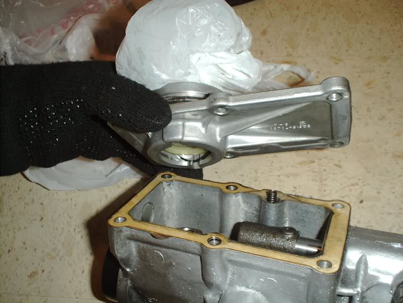
Next, I decided to check out the front transmission seal and the transmission front cover assembly.
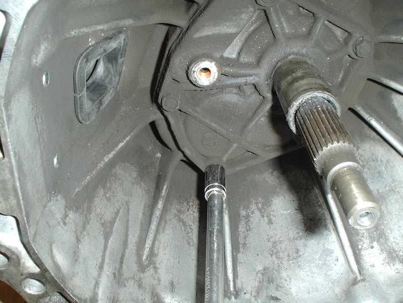
Use a 12mm socket to remove 5 bolts here...
and the front cover assembly comes off.
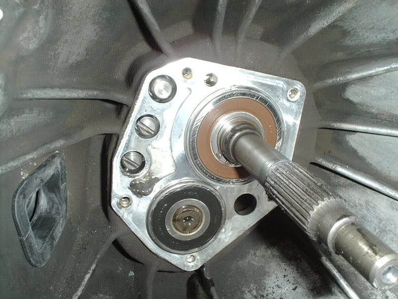
The seals look fine but if I do decide to replace them does anyone know how I can get them off because there is no where to grab at them like the other seals. I searched but couldn't come up with anything.
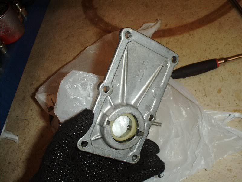
The front cover...
and gasket.
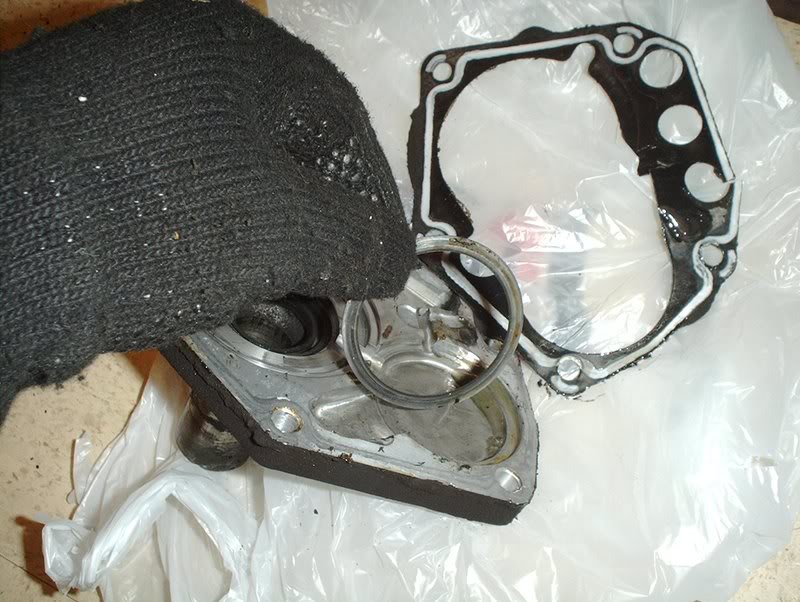
There's also a O-ring on the underside.
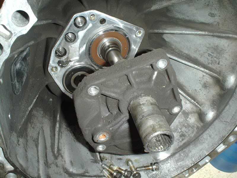
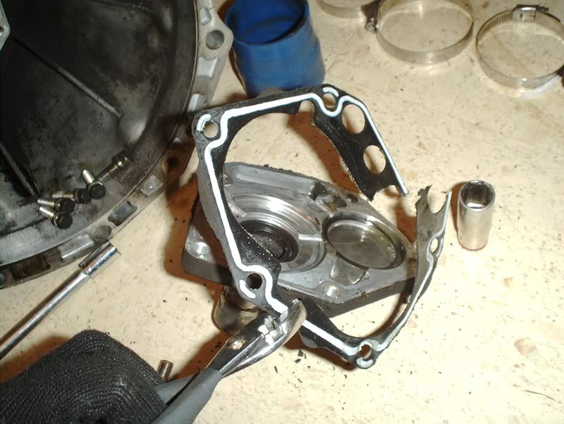
For the gearbox you need a 12mm socket...
to remove 6 bolts and off it comes.
Underside shot.
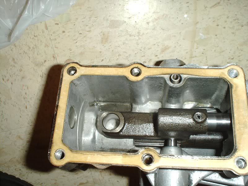
Inside shot, really interesting to see the inside of the tranny which is another reason why I decided to check this stuff out.
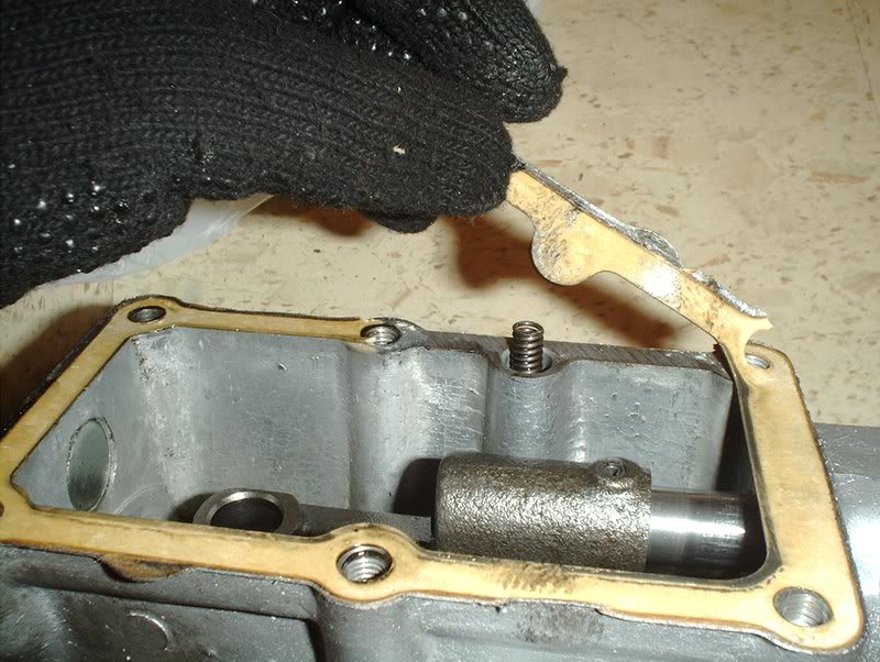
Also going to replace this gasket.

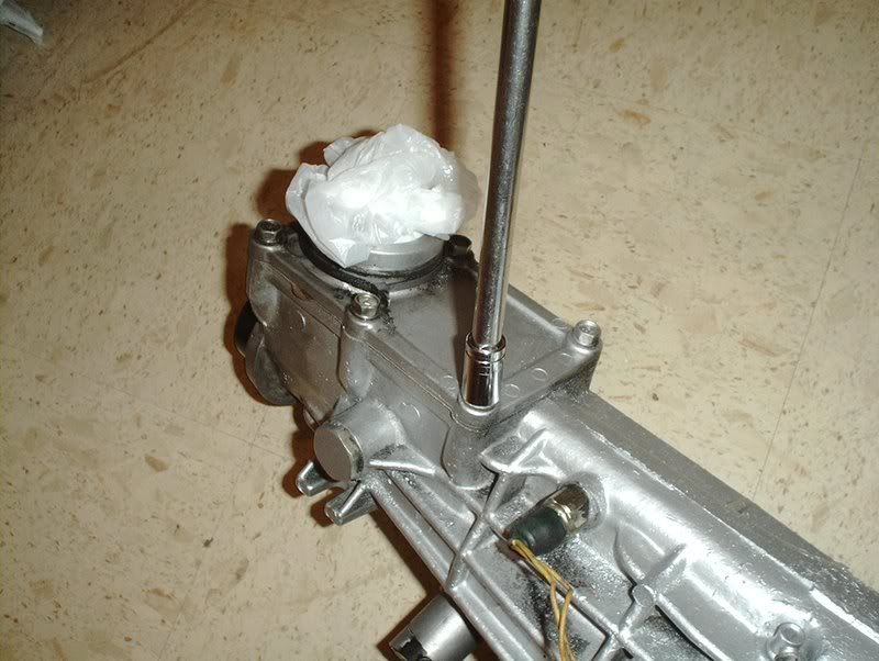
Finally I will also replace the rear transmission seal.
PARTS ON THE WAY TO BE CONTINUED......
Tools needed:
Socket wrench
Socket extension
12mm socket
17mm socket
I had a broken clutch pivot ball so I started by removing that.
All you need is a 17mm deepwell socket to remove it.
Next, I decided to check out the front transmission seal and the transmission front cover assembly.
Use a 12mm socket to remove 5 bolts here...
and the front cover assembly comes off.
The seals look fine but if I do decide to replace them does anyone know how I can get them off because there is no where to grab at them like the other seals. I searched but couldn't come up with anything.
The front cover...
and gasket.
There's also a O-ring on the underside.
For the gearbox you need a 12mm socket...
to remove 6 bolts and off it comes.
Underside shot.
Inside shot, really interesting to see the inside of the tranny which is another reason why I decided to check this stuff out.
Also going to replace this gasket.
Finally I will also replace the rear transmission seal.
PARTS ON THE WAY TO BE CONTINUED......
05-08-2008, 10:07 AM
#163
Contributing Member
Thread Starter
Join Date: Sep 2002
Location: Starkville, MS.
Posts: 1,192
Power Steering Pump Installation???...
I attempted to put my power steering pump on today.
Tools needed:
Socket wrench
Socket extension
12mm socket
14mm socket
Old sock/rag
Rubber mallet...you'll see why later.
I originally received a HICAS P/S pump with this engine set but I don't have HICAS on my car. I could have used it anyway because I found out(thanks to Bumnah and Durdan) that you can easily modify a HICAS pump to non-HICAS status.
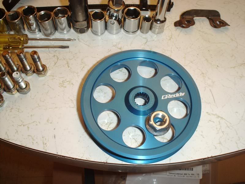
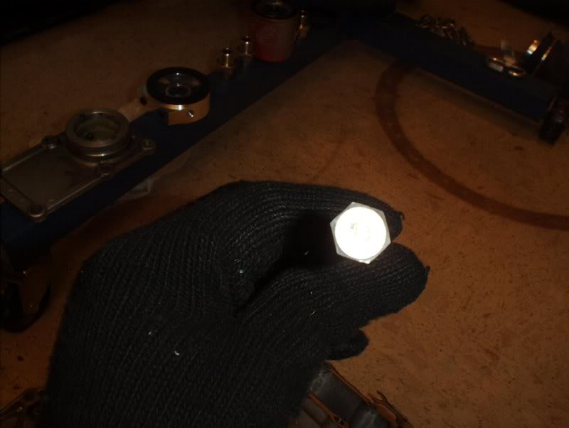
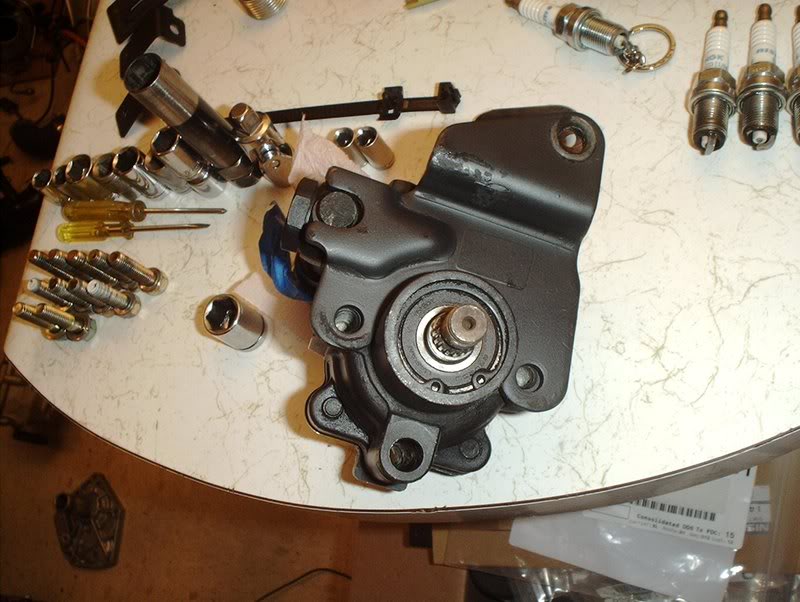
I also got a set of lightweight pullies to use on this engine and for the life of me, I can't figure out how you could remove the pulley from a HICAS pump as it's not held on with a nut like the other pumps for the SR and KA.
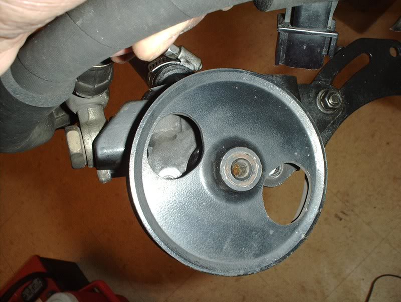
How do you remove this pulley?????
I did read how you could use a KA24DE pump with a non-HICAS SR pump bracket though so after tracking one down from a forum member I attempted to put this setup together.
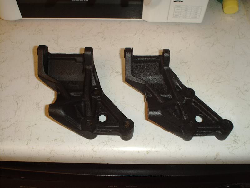
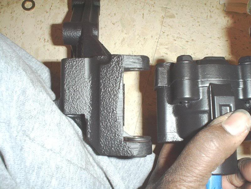
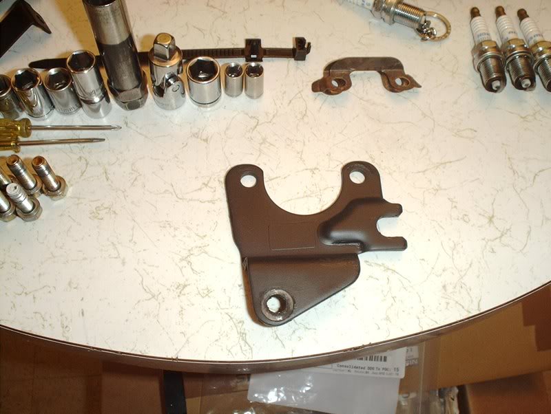
As you can see here the SR non-HICAS and HICAS pump brackets are slightly different.
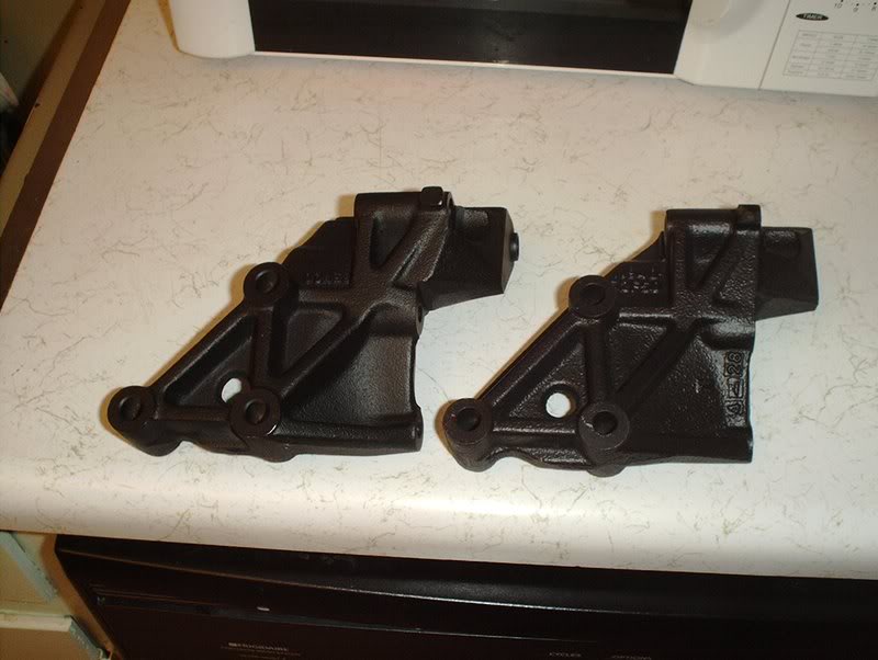
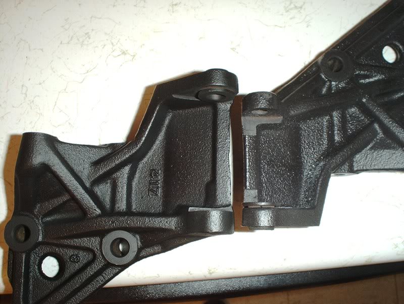
The non-HICAS SR bracket on the left is considerably larger than the non-HICAS bracket at the pump mounting point as you can see here.
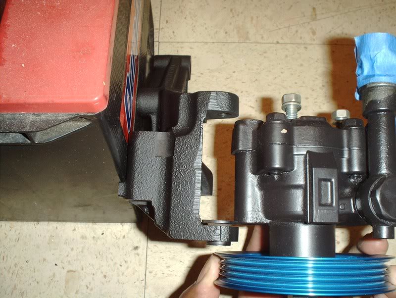
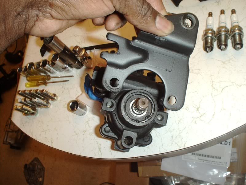
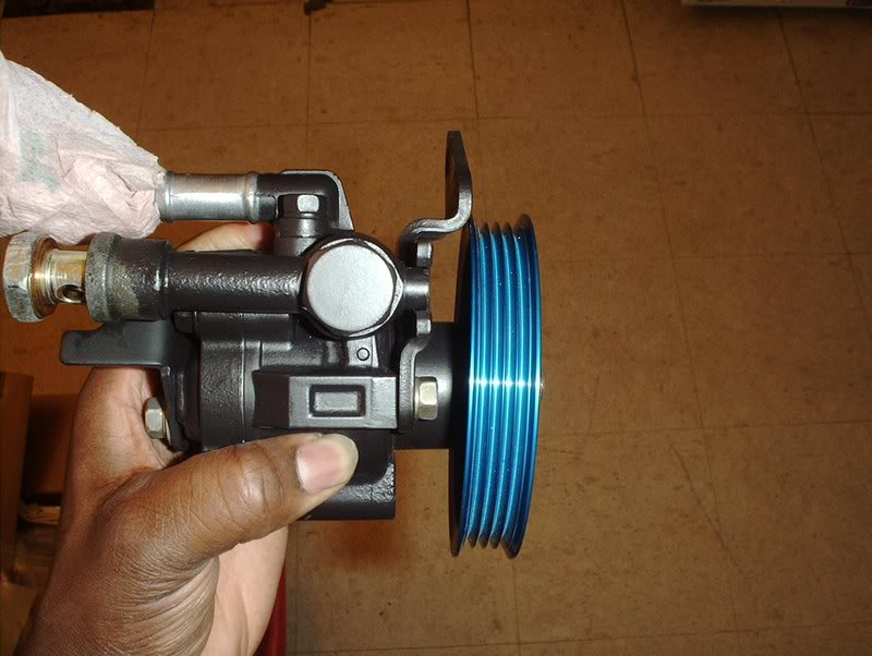
The KA24DE pump with the SR non-HICAS bracket...
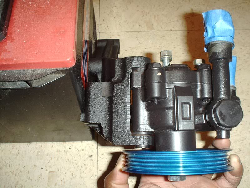
fits perfectly.
Here is where I tried to mount the KA24DE P/S pump on the HICAS bracket...it's too small.
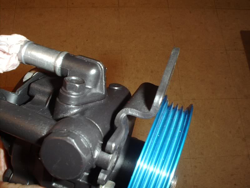
Now it's time to put the pulley on the pump.
If you broke your pump down like I did, make sure you put all brackets back on. This one goes on the rear of the pump...
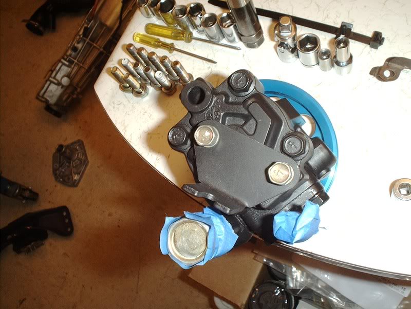
like so. It has a slot for the tab on the banjo line part of your P/S pressure hose.
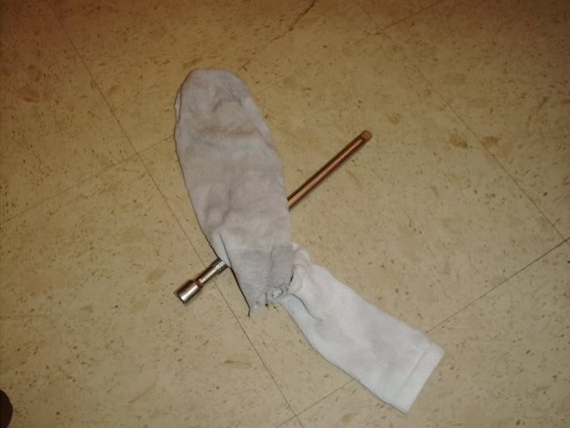
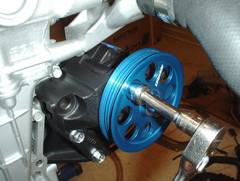
I went ahead and put the pulley on the pump, this is where the socket extension and old sock came into play.
Since the pulley will spin, you will need some way to get some leverage in order to tighten and torque the nut down when you install the pulley.
I took a socket extension and in order to keep the extension from damaging the pulley by rubbing up against it, I put something soft around the extension.
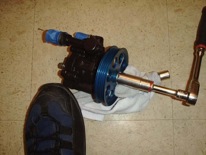
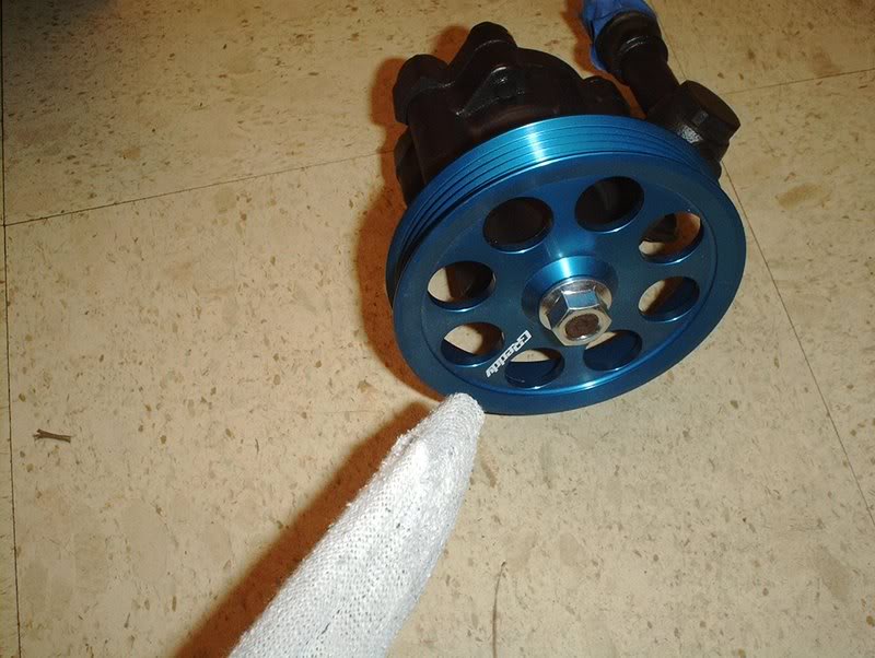
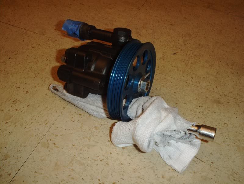
Stick the extension through one of the holes in the P/S pulley and you can use your foot to hold the pulley steady while you tighten and torque it to 40-50ft.lbs.
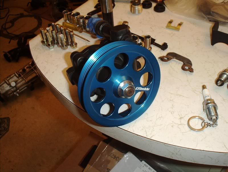
Done!
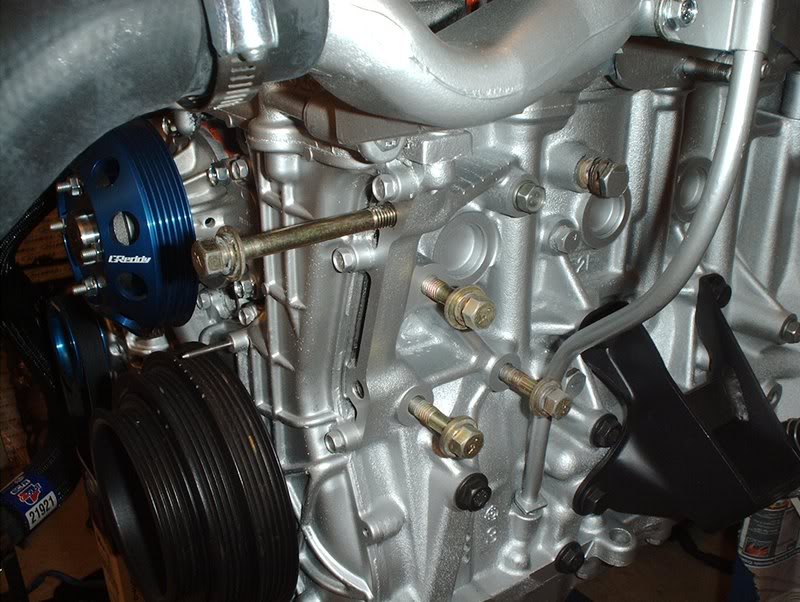
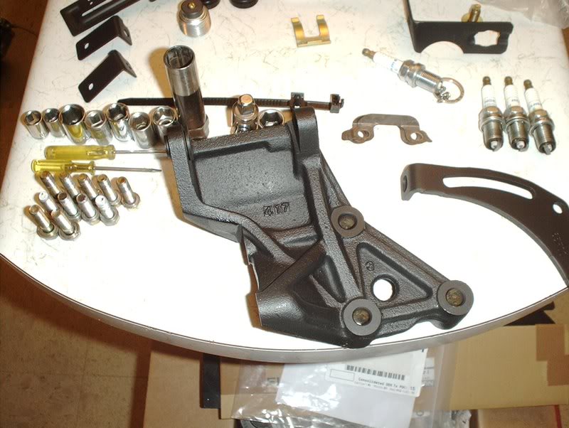
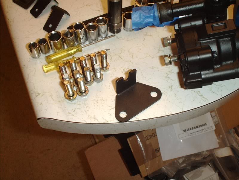
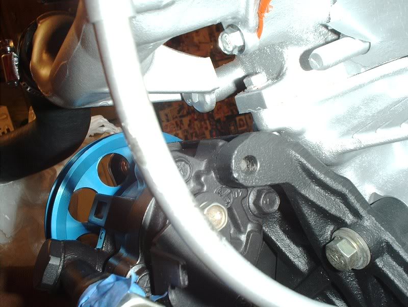
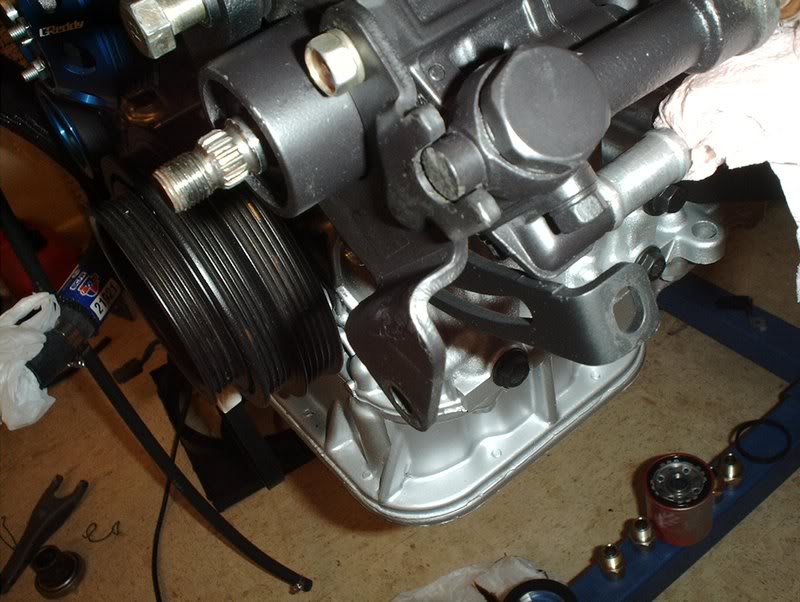
Next, you will need to mount the P/S bracket back on the block here.
Use a 14mm socket for the three bolts here and torque to 33-44ft.lbs. If you managed to mix up some of your bolts like I did then the bolts that you use for this have 7 on the head.
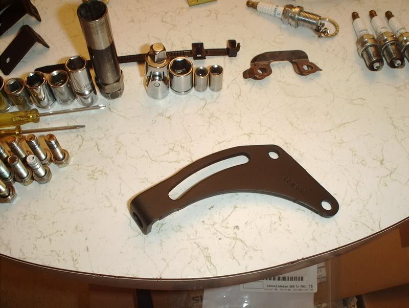
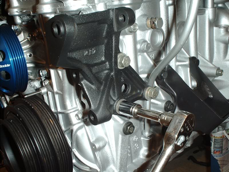
Next, take the tensioner bracket...
and use a 12mm socket to put two bolts here. If you don't use the OEM bolts you can substitute M8-1,25X20MM from the parts store. Torque the bolts to 12-16ft.lbs.
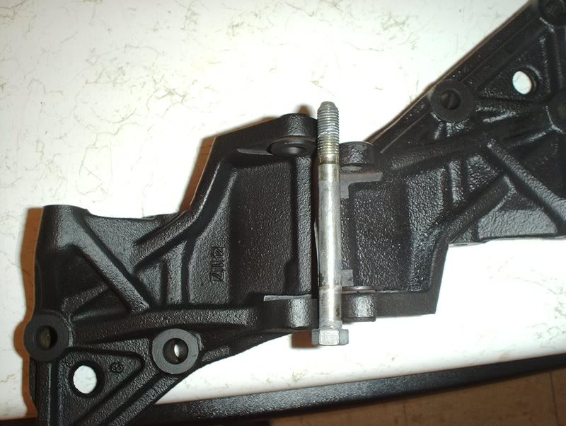
The extra long bolt that you will use to mount the P/S pump to the bracket has 7B on the head, you can't make it out in this pic but that's what it says.
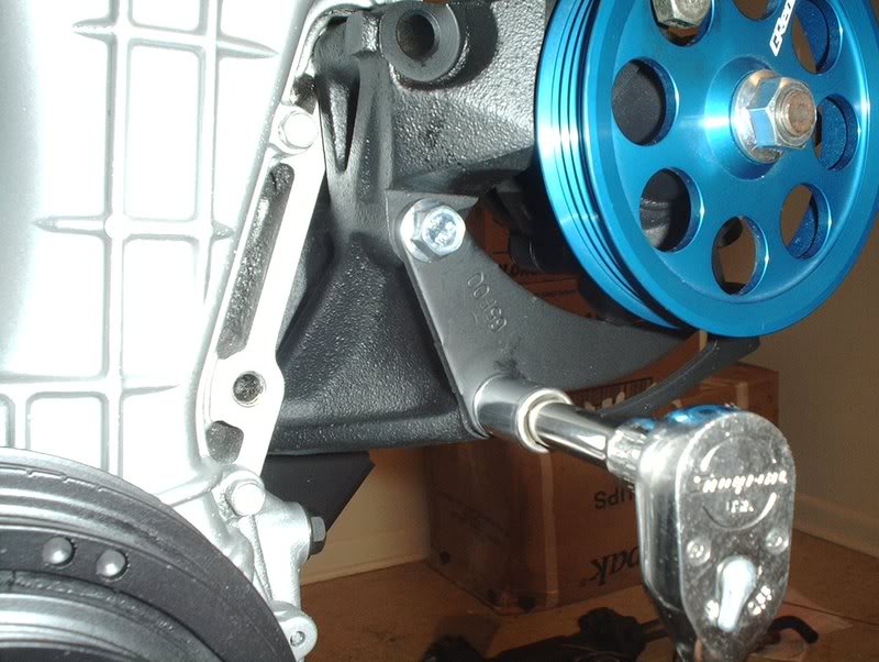
Spin one of the holes in the pulley and you can insert the bolt through it and into the bracket. Use a 14mm socket to tighten the bolt...
and torque to 23-31ft.lbs.
Am I finished you ask? Painfully no!
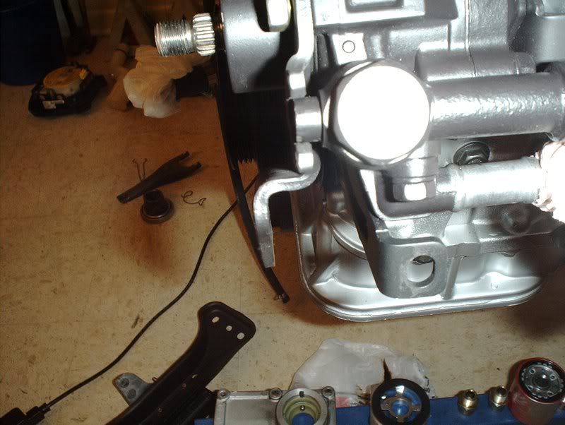
It was at this point that I realized that I messed up and left a part off.
This part that the tensioner bracket bolts connect to. Without this part on the P/S pump you can't adjust the tension on the P/S belts...doh! I had to take the pump back off and remove the pulley. After taking the nut off the pulley it's kind of hard to pull the pulley back off the pump so just grab a rubber mallet and whack the back of the pulley and it comes off quite easily without damaging the pulley.
Take the bracket...
put it on like so and bolt it down. Torque the bolts to 10-13ft.lbs.
Sadly after doing this I realized that the KA pump with the SR bracket was not going to work at least not the way I thought it would.
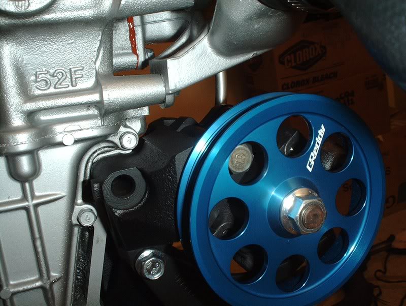
I mounted the pump on the P/S bracket and as you can see here the pump tensioner is no where near the bracket tensioner.
Not even close.
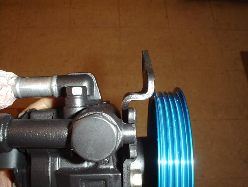
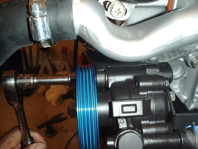
As for the pulley, it won't work either.
It makes contact...and it's not even close to halfway being threaded. I even broke out the OEM pulley and it's even wider than the Greddy unit so no go there.
KA P/S pump with SR bracket=FAIL
Unless someone sees something that I'm just not getting then I'm gonna track down a SR P/S pump to finish this up.
TO BE CONTINUED.......
Tools needed:
Socket wrench
Socket extension
12mm socket
14mm socket
Old sock/rag
Rubber mallet...you'll see why later.
I originally received a HICAS P/S pump with this engine set but I don't have HICAS on my car. I could have used it anyway because I found out(thanks to Bumnah and Durdan) that you can easily modify a HICAS pump to non-HICAS status.
I also got a set of lightweight pullies to use on this engine and for the life of me, I can't figure out how you could remove the pulley from a HICAS pump as it's not held on with a nut like the other pumps for the SR and KA.
How do you remove this pulley?????
I did read how you could use a KA24DE pump with a non-HICAS SR pump bracket though so after tracking one down from a forum member I attempted to put this setup together.
As you can see here the SR non-HICAS and HICAS pump brackets are slightly different.
The non-HICAS SR bracket on the left is considerably larger than the non-HICAS bracket at the pump mounting point as you can see here.
The KA24DE pump with the SR non-HICAS bracket...
fits perfectly.
Here is where I tried to mount the KA24DE P/S pump on the HICAS bracket...it's too small.
Now it's time to put the pulley on the pump.
If you broke your pump down like I did, make sure you put all brackets back on. This one goes on the rear of the pump...
like so. It has a slot for the tab on the banjo line part of your P/S pressure hose.
I went ahead and put the pulley on the pump, this is where the socket extension and old sock came into play.
Since the pulley will spin, you will need some way to get some leverage in order to tighten and torque the nut down when you install the pulley.
I took a socket extension and in order to keep the extension from damaging the pulley by rubbing up against it, I put something soft around the extension.
Stick the extension through one of the holes in the P/S pulley and you can use your foot to hold the pulley steady while you tighten and torque it to 40-50ft.lbs.
Done!
Next, you will need to mount the P/S bracket back on the block here.
Use a 14mm socket for the three bolts here and torque to 33-44ft.lbs. If you managed to mix up some of your bolts like I did then the bolts that you use for this have 7 on the head.
Next, take the tensioner bracket...
and use a 12mm socket to put two bolts here. If you don't use the OEM bolts you can substitute M8-1,25X20MM from the parts store. Torque the bolts to 12-16ft.lbs.
The extra long bolt that you will use to mount the P/S pump to the bracket has 7B on the head, you can't make it out in this pic but that's what it says.
Spin one of the holes in the pulley and you can insert the bolt through it and into the bracket. Use a 14mm socket to tighten the bolt...
and torque to 23-31ft.lbs.
Am I finished you ask? Painfully no!
It was at this point that I realized that I messed up and left a part off.
This part that the tensioner bracket bolts connect to. Without this part on the P/S pump you can't adjust the tension on the P/S belts...doh! I had to take the pump back off and remove the pulley. After taking the nut off the pulley it's kind of hard to pull the pulley back off the pump so just grab a rubber mallet and whack the back of the pulley and it comes off quite easily without damaging the pulley.
Take the bracket...
put it on like so and bolt it down. Torque the bolts to 10-13ft.lbs.
Sadly after doing this I realized that the KA pump with the SR bracket was not going to work at least not the way I thought it would.
I mounted the pump on the P/S bracket and as you can see here the pump tensioner is no where near the bracket tensioner.
Not even close.
As for the pulley, it won't work either.
It makes contact...and it's not even close to halfway being threaded. I even broke out the OEM pulley and it's even wider than the Greddy unit so no go there.
KA P/S pump with SR bracket=FAIL
Unless someone sees something that I'm just not getting then I'm gonna track down a SR P/S pump to finish this up.
TO BE CONTINUED.......


